EasyManua.ls Logo

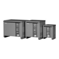
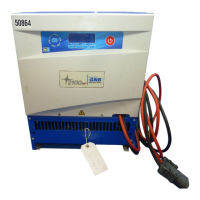
GNB SCR SERIES - User Manual

GNB SCR SERIES
68 pages
Print Icon
To Next Page IconTo Next Page
Loading...
SCR SERIES CHARGERS
SCR SERIES CHARGERS
INSTALLATION & OPERATING
INSTRUCTIONS
FOR
SCR & SCRF SERIES
BATTERY CHARGER
WITH
SINGLE PHASE INPUT
Section 93.20
2011-11
JA0132-00
I & O MANUALS
I & O MANUALS

Table of Contents

Questions and Answers

  • J
    Jessica NelsonAug 12, 2025
    How to check AC secondary voltage on GNB Battery Charger?
    • M
      Michelle RodriguezAug 12, 2025
      If secondary voltages are much less than indicated, check AC secondary voltage on the main transformer (T1). Either T1 is at fault or the power regulating devices (SCR1 or SCR2) are faulty.
  • D
    David BrooksAug 16, 2025
    What to do if panel DC voltmeter of GNB Battery Charger does not indicate?
    • J
      jeremy02Aug 16, 2025
      If the panel DC voltmeter on your GNB Battery Charger doesn't show any reading, check the wiring for an open circuit. If the wiring is intact, consider replacing the meter.
  • B
    Benjamin AriasAug 20, 2025
    What to do if AC voltmeter indicates line voltage but not when connected to the output terminals of CB1 when closed in GNB Battery Charger?
    • K
      Kimberly MeyerAug 20, 2025
      If your AC voltmeter indicates line voltage, but not when connected to the output terminals of CB1 when closed, the circuit breaker is likely defective. De-energize the AC supply, remove the leads, and use a voltohmmeter to check for continuity between the circuit breaker terminals with the breaker manually closed.
  • E
    ellisdavidAug 23, 2025
    What to do if DC ammeter indicates zero on GNB Battery Charger?
    • P
      Patricia HansenAug 23, 2025
      If the DC ammeter reads zero, start by ensuring all connections are tight. The charger's DC ammeter may be open or shorted.
  • E
    ericmaciasAug 27, 2025
    How to measure feedback voltage on GNB Battery Charger?
    • A
      Adam MorrisAug 27, 2025
      If the MCU cannot function as intended or produces incorrect outputs, measure the feedback voltage from the slider of the 'FLOAT ADJUST' potentiometer (R3) to the control module board, because feedback circuit or related circuits are not functioning.
  • K
    Kevin RobinsonAug 31, 2025
    How to check AC ripple voltage on GNB Battery Charger?
    • T
      Travis StewartAug 31, 2025
      If you suspect issues with the filter capacitor, connect a sensitive AC voltmeter to the battery terminals and measure the AC ripple voltage because the R1 has opened and no longer serves as a bleeder.
  • F
    Felicia PerkinsSep 4, 2025
    What to do if voltage drop is higher or lower than nominal indication across current sensing resistor in GNB Battery Charger?
    • C
      Corey SimpsonSep 4, 2025
      If the voltage drop is higher or lower than the nominal indication across the current sensing resistor, replace the ammeter or shunt and recheck the voltage drop.
  • N
    norman76Sep 8, 2025
    How to check AC line source of GNB Battery Charger?
    • M
      Michael GarciaSep 8, 2025
      If there is no line voltage between TB1-L1 and TB1-L2, check the AC line back to its source.

Summary

SCR;SCRF SERIES BATTERY CHARGER SPECIFICATIONS

AC Input Current

Specifies the maximum AC input current ratings for various models.

DC Output Ratings

Details the DC output voltage and current capabilities.

IMPORTANT SAFETY INSTRUCTIONS

General Safety Precautions

Covers essential safety rules, handling of explosive gases, and personal protection.

SECTION II INSTALLATION AND OPERATION

Safety Notice

Important safety warnings and precautions for operating the charger.

Application Overview

Details the intended applications and capabilities of the SCR/SCRF series chargers.

Installation Procedures

Covers location, AC/DC wiring, and input power requirements for proper installation.

Placing Charger in Service

Step-by-step guide for energizing and initial setup of the battery charger.

Float and Equalize Adjustments

Procedures for setting float and equalize voltages using potentiometers.

Manual Equalize Timer

Explains the function and use of the optional manual equalize timer.

SECTION III TROUBLESHOOTING

Troubleshooting Caution Notice

Critical safety precautions to be taken before troubleshooting the charger.

Troubleshooting Procedure

General procedure for identifying and locating faults within the battery charger.

Component Testing Procedures

Guides for testing individual electrical components like wiring, transformers, and diodes.

SECTION IV SYSTEM ADJUSTMENTS

Voltage Adjustments and Response

Procedures for adjusting float and equalize voltage outputs and checking system response.

Current Limit Response and Adjustment

How to check and adjust the current limit and troubleshoot malfunctions.

SECTION V CUSTOMER OPTIONS

Ground Detection Circuits

Explains the purpose and various methods of ground detection systems.

Alarm Options

Covers various alarm functionalities like AC failure, voltage, charger failure, and discharge alarms.

Timer and Control Options

Describes equalize timers and manual float/equalize switches for charging mode control.

Monitoring and Special Function Options

Covers options like ammeters, voltage shutdown, parallel operation, and CASM.

SECTION VI COMPONENT DESCRIPTION

Mainframe Component Descriptions

Lists and describes components of the single-phase mainframe.

Option Component Descriptions

Lists and describes components for charger options.

SECTION IX REPLACEMENT PARTS

Mainframe Electrical Ratings and Parts

Lists electrical ratings and replacement part numbers for the mainframe.

Option Replacement Parts

Lists replacement part numbers for various charger options.

SECTION X MANUAL SPECIFICATIONS

Document Number and Revision

Identifies the internal part number and revision history of the manual.

On-Line Availability and Drawings

Information on obtaining electronic versions of the manual and standard drawings.

Parts Data Package and Custom Drawings

Information on custom parts data packages and drawing availability.

Preventive Maintenance Procedure

Standard Maintenance Checks

Covers cleaning, electrical checks, voltage/ripple measurements, and control tests.

Optional Maintenance Checks

Covers checks for alarm settings and remote wiring integrity.

Long-Term Maintenance

Guidance on replacing capacitors as part of long-term maintenance.

GNB SCR SERIES Specifications

General IconGeneral
Charging Stages3-Stage (Bulk, Absorption, Float)
Output Voltage12/24/48V DC
Battery TypeAGM, Gel
Operating Temperature-20°C to 50°C
MountingWall Mount
Agency ApprovalsUL, CE
ProtectionReverse Polarity, Over Voltage, Over Current, Short Circuit, Over Temperature
Storage Temperature-40°C to 70°C
Humidity5% to 95% non-condensing
AltitudeUp to 2000m

Related product manuals