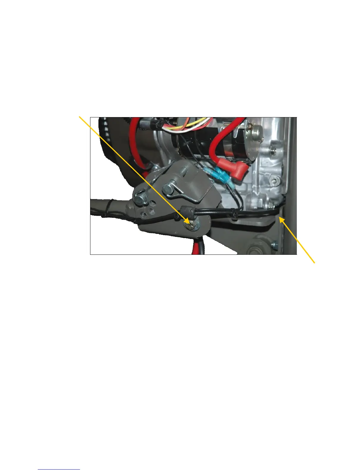
10. The 3/8”x 2-1/2” bolt indicated by the arrow in the figure below is the pivot point
for the Adjustable/Floating handle. Remove the bolt and insert the handle into
the engine-mounted handle bracket. Reinstall the bolt into the bracket, passing it
through the hole at the end of the handle. Be sure to include the wire loom to
secure the cables as it was shipped. Install the washer and nut and tighten the
nut firmly or until a slight amount of drag can be felt while pivoting the handle up
and down from the grip. Attach the safety kill switch wires to the mating
terminals on the engine.
23 Vanguard Shown
11. Route the throttle cable through the opening near the lower rear section of the
engine and attach the throttle cable to the engine linkage as shown in the
following photos on page 3. A flat spot near the end of the black cable should be
visible, indicating the position where it was originally clamped at the factory.