6
gpelectric.com
GP-FLEX-100
GP-FLEX-200
GP-FLEX-100E
2. Run the solar module power cable to the location of The GP-PWM-30. Do not connect the wires
to the controller or the batteries. Identify the polarity of the wires located on the battery and
solar module (positive and negative). Use coloured tape or mark wire ends with tags. Contacting
the leads of the controller in reverse polarity, however brief, will cause the controller to go into lock
out mode and the solar controller will need to be reset.
3. Kits include a fuse holder with an inline 30A fuse to protect the wire between the battery and solar
controller. Install your inline fuse as close to the battery as possible before connecting the solar
controller to the battery terminal. See Figure 2: “12 Volt Battery Connected to Solar Controller with
Inline Fuse”.
4. Wire the controller according to the terminal identication on the back of controller, starting with the
battery connections. Tighten the positive and negative battery connections and then set the battery
type (see controller manual for instruction). Then, connect and tighten the positive and negative solar
module connections.
5.1 Mounting The GP-PWM-30 Controller
The GP-PWM-30 should be mounted in a location relatively close to the battery, but easily seen for
monitoring system operation. Wires must be run from the solar module to the controller and then to the
battery. The GP-PWM-30 is designed to be ush mounted on the side of a cabinet or wall where the
wiring can be accessed from the back. Allow two to three inches behind the unit. The controller should
be mounted indoors, in a dry location.
1. Select a suitable location for the installation of the controller. Run the power cable from the solar
module to the location selected.
2. Use the template included in the GP-PWM-30 Manual to mark the four mounting holes and the
“cutting line for ush mounting”. Drill the mounting holes. Use a keyhole or jig saw to cut along the
rectangular outline you marked.
3. Wire the controller as shown in the GP-PWM-30 Manual. Use the leftover power cable to connect
the controller to the batteries.
4. Mount the controller to the wall using the four screws provided in the GP-PWM-30 box. Ensure the
back of the controller is protected from damage by any object.
6.0 Connecting to the Battery & Solar Array
It is recommended to connect directly to the battery wherever possible. You can also connect to the
converter/charger where the battery positive and negative wires connect to the converter.
1. Clean all corrosion from battery terminals before proceeding. Crimp ring terminals onto the negative
and positive wires of the power cable to be attached to the battery.
2. Attach the negative (black) wire’s 3/8” ring terminal to the RV battery. Check all electrical connections
and apply a protective coating to battery terminals.
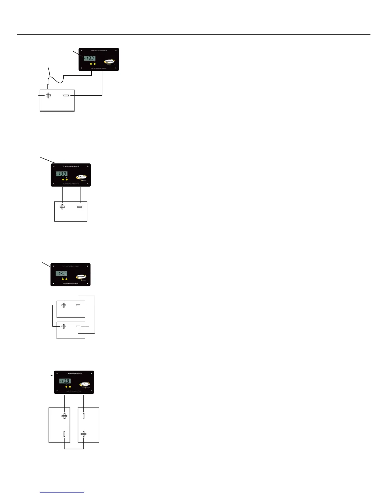
6.1 Typical Battery Connection
1. Single 12 Volt battery connection (See Figure 3)
2. Parallel 12 Volt battery connection (See Figure 4)
3. 2 x 6 Volt series battery connection (See Figure 5)
7.0 Disclaimer of Liability & Warranty
1. Go Power! warrants the Solar Flex
TM
Kit for a period of one (1) year from the date of shipment from
its factory. This warranty is valid against defects in materials and workmanship for the one (1) year
warranty period. It is not valid against defects resulting from, but not limited to:
• Misuse and/or abuse, neglect, or accident
• Exceeding the unit’s design limits
• Improper installation, including, but not limited to, improper environmental protection and
improper hook-up
• Acts of God, including lightning, oods, earthquakes, re, and high winds
• Damage in handling, including damage encountered during shipment
2. This warranty shall be considered void if the warranted product is in any way opened or altered. The
warranty will be void if any eyelet, rivets, or other fasteners used to seal the unit are removed or
altered, or if the unit’s serial number is in any way removed, altered, replaced, defaced or rendered
illegible.
Figure 3
Single 12 Volt Battery
12 Volt Conguration
Solar
Controller
Negative
Connection
Positive
Connection
Figure 4
Solar
Controller
Positive
Connection
Negative
Connection
Two 12 Volt Batteries
12 Volt Parallel Conguation
Solar
Controller
Figure 5
Positive
Connection
Negative
Connection
Two 6 Volt Batteries
12 Volt Series Conguation
Fuse
Positive
Connection
Negative
Connection
12 Volt Battery Connected to
Solar Controller with Inline Fuse
Figure 2
Solar
Controller
 Loading...