EasyManuals Logo

Go Power GP-PWM-25 User Manual

Go Power GP-PWM-25
18 pages
To Next Page IconTo Next Page
To Previous Page IconTo Previous Page
Page #17 background imageLoading...
Page #17 background image
Owner’s Manual | GP-PWM-25 Regulator
17
© 2009 Carmanah Technologies Corporation
Last revised: July 2009
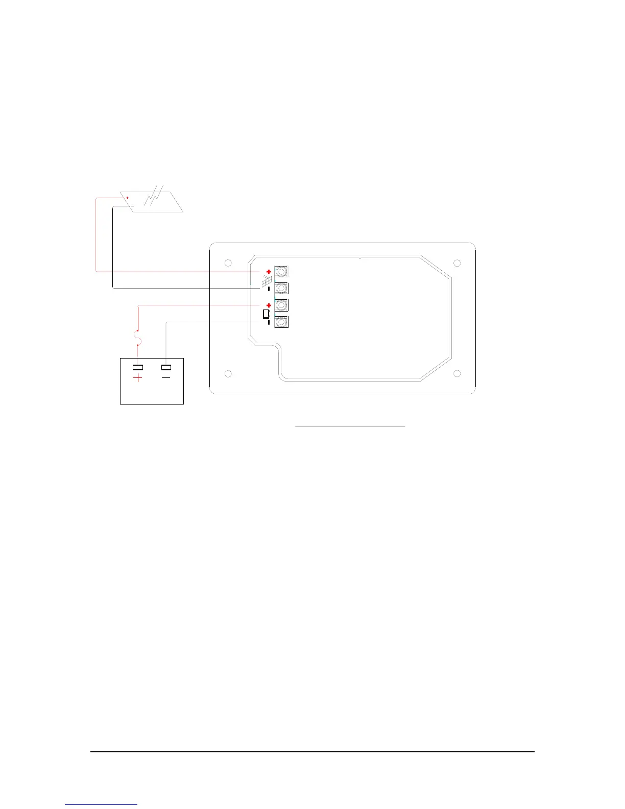
12.0 Wiring Diagram
SUGGESTED FUSE SIZE
#14 WIRE = 15 AMP FUSE
#12 WIRE = 20 AMP FUSE
#10 WIRE = 30 AMP FUSE
NOTE:
THE FUSE IS INTENDED TO PROTECT
THE WIRE.
THE GP-PWM-25 IS BASED ON A 25 AMP MAX FOR THE
TOTAL IMP OF THE SYSTEM.
E.G. THREE MODULES IN PARALLEL WITH AN IMP OF 7
AMPS EACH EQUALS A TOTAL IMP OF 21 AMPS.
MOST SOLAR MODULES LIST THE IMP ON THEIR
SPECIFICATIONS LABEL.
SOLAR ARRAY
BATTERY BANK
FUSE

Questions and Answers:

Question and Answer IconNeed help?

Do you have a question about the Go Power GP-PWM-25 and is the answer not in the manual?

Go Power GP-PWM-25 Specifications

General IconGeneral
BrandGo Power
ModelGP-PWM-25
CategoryBattery Charger
LanguageEnglish

Related product manuals