Do you have a question about the Go Power GP-TS-30 and is the answer not in the manual?
Covers disconnecting power, choosing mounting locations, electrical preparation, and physical mounting.
Step-by-step guide for making electrical connections to the transfer switch.
Explains the delay feature and how to bypass it using a jumper.
Details wiring configurations for connecting the switch between power cord and generator.
Describes installation for connecting the switch between an inverter and another power source.
Explains setup for hybrid systems using the transfer switch for designated circuits.
Discusses causes, effects, and solutions for general and localized low voltage conditions.
Addresses wiring interference with relay operation and issues with burned/pitted relay contacts.
Steps to test circuit board operation and perform hi-pot tests for system integrity.
Recommendations for starting and stopping the generator to prolong equipment life.
Covers cautions regarding flammable liquids and warnings about shock hazards and ignition protection.
Outlines the product warranty terms and limitations.
Provides guidance on obtaining technical support and returning defective products.
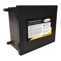
The Go Power! 30-amp Transfer Switch (TS-30) is designed to provide automatic power switching between two distinct 120-volt AC input sources. These sources can include external power cords, onboard generators, or onboard inverters. The primary function of the TS-30 is to sense the availability of these power supplies and automatically select the appropriate one for your electrical system. This automation ensures a seamless transition between power sources, enhancing convenience and reliability for users.
The TS-30 offers flexibility in its installation, making it suitable for various electrical setups. It can be installed at the electrical entry point of an RV, specifically on the line side of the main distribution panel. Alternatively, it can be positioned on the load side of the panel, between the main panel and a sub-panel. This dual installation capability allows the transfer switch to manage either the entire electrical load of the system or only designated circuits, depending on the user's specific needs and the complexity of their electrical setup. This adaptability ensures that the TS-30 can be integrated into a wide range of mobile power systems.
When installing the TS-30, several key steps and considerations are outlined to ensure safe and effective operation. Before any work begins, it is crucial to disconnect all power sources. This includes turning off the generator, unplugging the external power cord, and shutting off any inverters. This safety precaution is paramount to prevent electrical shock and ensure the safety of the installer.
Mounting the TS-30 requires careful selection of a location. The unit should be placed on any interior surface where it will be protected from direct weather exposure. The chosen location must also remain accessible after installation to facilitate future servicing or maintenance. Ideal mounting locations often include under-counter cabinets, below closet compartments, inside bed pedestals or cabinets, overhead cabinets, or under-floor storage compartments accessible from the vehicle exterior. However, it is explicitly cautioned not to mount the transfer switch in an engine compartment, under kitchen sink drains or water pipes, within the battery compartment, or any compartment designed for the storage of flammable liquids such as gasoline. This is because the transfer switch is not ignition protected, and arcing during normal operation could ignite flammable vapors, leading to property damage, serious injury, or death.
Electrical preparation involves using any numbered knockout on the TS-30 for cable entry, selecting one that best facilitates installation and service. The unit is then mounted securely to a solid surface using screws through the provided holes in the bottom corners, ensuring it can withstand vehicle operation.
For electrical connections, an 8-gauge chassis ground wire must be attached to the transfer switch ground bar, with a direct access hole provided for convenience. Proper identification of wire conductors is essential: bare or green for ground, white for neutral, and black for hot. The outer jacket of incoming cables should be stripped, and insulation removed from the ends of copper conductors. Cables are then inserted through clamps, which are not tightened until all connections are made. Internal ground wires should be routed around the lower area of the enclosure and secured to the ground bar, away from electrical contacts to prevent short-circuits. Terminals for ground wires should be tightened to a minimum of 20 inch-pounds. Neutral (white) and hot (black) wires are then connected. For wire leads, insulation is stripped 0.5 inches, and the bare wire is inserted into the vacant hole, secured by dropping the lever. Finally, cable clamps on the switch enclosure are tightened, and the lid is attached, designed to snap on securely.
The TS-30 incorporates a timing delay feature when switching between power sources. This delay can be eliminated by placing a jumper across two specific pins on the timing board within the unit. This feature is particularly useful in hybrid systems where a line from the main distribution panel is routed through a second transfer switch to power only specific circuits in a coach. All connections must be verified and tightened to ensure proper operation.
For installations between a power cord and a generator, the power cord leads are connected to terminals 7 and 8 (normally closed contacts on the narrow end of the relay). Generator leads are connected to terminals 5 and 6 (normally open contacts on the shoulders of the relay). The output to the panel is connected to terminals 3 and 4 (on the wide end of the relay). The time delay module provides a brief warm-up period for generators before supplying the load. A critical note is to ensure that the inverter never provides power to the charger; chargers should be wired to the Transfer Switch as per the provided diagrams.
In installations between an inverter and an alternating source (Configuration C), the inverter is connected to terminals 7 and 8. The other power supply (output from a prior power cord/generator transfer switch) is connected to terminals 5 and 6. Output terminals remain consistent. This configuration allows the other supply to dominate the inverter, meaning the inverter operates only when other power supplies are absent, which is ideal for inverter use. For systems with three AC sources, two transfer switches are required.
For hybrid systems with designated circuits (Configuration D), the TS-30 can be installed between the inverter (default) and a circuit panel supplied by a larger amp alternating power supply (dominant). The inverter connects to terminals 7 and 8, the 30-amp branch circuit to 5 and 6, and the designated circuit panel to output terminals 3 and 4. In this setup, the inverter supplies the load only when the 50-amp power supply is absent, and only the load designated to the 30-amp branch circuit is supplied. The timer delay bypass switch on the TS-30 should be in the ON position.
Operational testing involves a sequence of steps to verify the transfer switch's functionality. First, plug in the power cord; if main panel circuit breakers are on, RV load should operate normally. Then, unplug the power cord. Next, start the generator. A pre-programmed 20-30 second delay allows the generator to warm up. After the delay, the switch should engage with an audible click, and the RV load should operate normally. Shut down the generator; the switch should disengage without chatter, with an audible click. Then, plug in the power cord and start the generator again. After the delay, the switch should automatically transfer power from the power cord to the generator, indicated by an audible click. Shut down the generator and unplug the power cord. For three-power-supply arrangements, plug in the power cord, start the generator, and turn on the inverter. The switch will prioritize the generator, then transfer to the power cord when the generator is shut down, and finally to the inverter when the power cord is unplugged. The inverter is always selected in the absence of other supplies.
Troubleshooting addresses common issues like low voltage. Low voltage is detrimental to appliances and can cause contactor points to "chatter," leading to damage. Damaged switches require factory replacement. General low voltage can stem from inadequate RV park wiring (brownouts), which can be identified with a voltmeter. In such cases, using the generator until park voltage improves is recommended. Localized low voltage can result from using an overly long or undersized extension cord. This can be identified by measuring voltage at contactor terminals while manually holding the plunger down during an inrush cycle (e.g., air conditioner startup). Correcting the low voltage situation is crucial.
Physical interference can also cause issues. Some models have wire nut connections that can interfere with relay operation if folded improperly. Visual inspection for free relay operation is advised.
Hi-pot testing (for manufacturing companies only) is performed to check for leakage or shorts. It should be done from the transfer switch output or main panel, not the generator input, as it can damage the time delay control module. All circuit breakers must be on, the generator off, and the power cord unplugged with prongs protected. Appliances that could be damaged must be disconnected. Hi-pot leads connect to the ground bar and output terminals (hot 1, hot 2, and neutral). If the test fails, the short must be isolated by systematically testing branch circuits.
Maintenance features include warnings about torqueing connections to prevent fire, shock hazards requiring qualified service personnel, and the importance of not mounting the TS-30 in compartments with batteries or flammable materials due to its lack of ignition protection.
The Go Power! 30-amp Transfer Switch comes with a two-year warranty covering defects in materials or workmanship under normal use. However, the warranty does not cover defects resulting from misuse, abuse, neglect, accidents, exceeding design limits, improper installation (including environmental protection and hook-up), acts of God (lightning, floods, earthquakes, fire, high winds), damage during shipment or installation, or outdoor weather exposure. For support, users can visit gpelectric.com for FAQs, use the online contact form or live chat, email techsupport@gpelectric.com, or return defective products to the place of purchase.
In summary, the Go Power! 30-amp Transfer Switch is a robust and versatile device designed to manage multiple AC power sources automatically. Its comprehensive installation guidelines, operational testing procedures, and troubleshooting advice ensure reliable performance and safety. The device's ability to seamlessly switch between power sources, coupled with its flexible installation options, makes it an essential component for mobile power systems, providing convenience and peace of mind for users. Adherence to all safety warnings and installation instructions is critical for optimal performance and longevity of the unit.
| Model | GP-TS-30 |
|---|---|
| Type | Transfer Switch |
| Amperage | 30 Amps |
| Voltage | 120V AC |
| Wiring | 3-Wire |