Home
Gobel
Battery Pack
GP-SR1-PC200
Page 41 (LED Indicator)
Gobel GP-SR1-PC200 - LED Indicator
42 pages
Manual
Save Page as PDF
To Next Page
To Next Page
To Previous Page
To Previous Page
Loading...
40
GP
-SR1-PC200
Owner’s
Manual
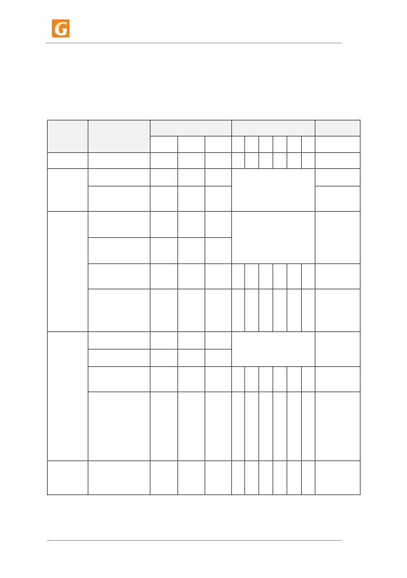
16.4.
LED Indica
tor
Ther
e are 9 LEDs,
1 fo
r Alarm,
1 for Run, 1 for On
, 6 for C
apacity
.
●
is solid lights,
▲
is flashing lights (0.25s-3.75s),
◆
is fla
shing lights (0.5s-
0.5s),
★
is flashing lights (0.5s-1.5s).
Action
State
State Lig
h
ts
SOC Lights
ON
RUN
ALM
6
5
4
3
2
1
Off
Sleep
/
/
/
/
/
/
/
/
/
Standby
Normal
●
▲
◆
On accor
ding to SOC
Alarm
●
▲
★
Low
V
oltage
Charge
Normal
●
●
/
On accor
ding to SOC
T
op SOC LED
◆
ALM
●
while
Over
V
oltage
Alarm
Alarm
●
●
★
Over Char
ge
P
rotection
●
●
/
●
●
●
●
●
●
T
emperatur
e
,
Over Curr
ent,
F
aulty
P
rotection
●
/
●
/
/
/
/
/
/
Stop
Charge
Dis-
Charge
Normal
●
★
/
Accordi
ng to SOC
Alarm
●
★
★
Over Disch
arge
P
rotection
●
/
/
/
/
/
/
/
/
Stop
Dischar
ge
T
emperatur
e
,
Over Curr
e
nt,
Short Cir
cuit,
Revers
e
Connection
,
F
aulty
P
rotection
●
/
●
Stop
Dischar
ge
F
aulty
F
aulty
/
/
●
/
/
/
/
/
/
Stop
Charge
&
Dischar
ge
40
42
Table of Contents
Main Page
Table of Contents
2
Information on this Document
4
Validity
4
Target Group
4
Content and Structure of this Document
4
Levels of Warning Messages
4
Symbols in the Document
5
Designation in the Document
5
Safety
6
Intended Use
6
Important Safety Instructions
6
Scope of Delivery
9
Battery System Overview
11
Battery System Description
11
Interface
11
Symbols on the System
12
Installation
13
Requirements for Installation
13
Installation
14
Electrical Connection
17
Overview of the Connection Area
17
Connection Diagram
17
Data Cable Connection
19
DC Connection
21
Commissioning
23
Configure the Battery System
23
Switch on the Battery System
23
Switch on and Commission the Inverter
23
Operation
25
Switch on the Battery System
25
Switch off the Battery System
25
Decommissioning
26
Extension
27
Troubleshooting
28
LED Light Designation for Errors
28
The Battery System Is Not Able to be Turned on or off
28
Maintenance and Storage
29
Cleaning
29
Maintenance
29
Disposal of the Battery System
30
Technical Parameters
31
Contact Information
33
Appendix
34
Configure BMS of Battery Module
34
ADS Table of DIP Switch
38
Designation of RS232, RS485 and CAN Ports
39
LED Indicator
41