Do you have a question about the Goldstar WG1205R and is the answer not in the manual?
Explains icons and notations used for safety warnings and general information.
Covers essential warnings about operation, modification, and placement to prevent hazards.
Explains icons and notations used throughout the manual for clarity.
Provides the physical measurements of the air conditioner unit.
Guides on choosing the best location for unit placement to ensure performance.
Lists essential checks to verify before and after unit installation.
Specifies necessary window dimensions and preparations for secure installation.
Covers preparing the unit's chassis and mounting the main cabinet.
Details steps for attaching the sill support and cabinet to the window frame.
Covers sliding the unit, attaching seals, and securing grilles for completion.
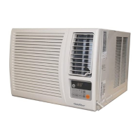
Identifies and explains the functions of the unit's main controls.
Details the operation and features of the remote controller.
Provides instructions for inserting batteries into the remote controller.
Details the process of removing mechanical parts like grille, cabinet, and control box.
Covers removal of air-related parts like guides, blowers, and fans.
Outlines the removal of motor, overload protector, and compressor.
Explains how to remove switches, power cords, and capacitors.
Details removal of refrigerant system parts like condenser, evaporator, and capillary tube.
Presents electrical wiring connections for the rotary switch model.
Shows the electrical circuit for the touch and remote control model.
Illustrates the detailed electronic control circuitry.
Identifies placement of components on the main printed wiring board.
Describes the arrangement of components within the refrigeration system.
Guides on diagnosing and resolving issues causing insufficient cooling.
Provides troubleshooting steps for when the unit fails to power on.
Details electrical diagnostics for non-operation and related circuit issues.
Addresses problems with compressor and fan operation, including failure to start or continuous running.
Troubleshoots remote control failures and abnormal display board behavior.
Solves issues related to fan motor operation, noise, and compressor inactivity.
Addresses compressor overload, insufficient cooling, and excessive noise troubleshooting.
| Type | Window |
|---|---|
| Power Consumption (Cooling) | 1150W |
| Weight | 38 kg |
| Cooling Capacity | 12000 BTU/h |
| Refrigerant | R22 |