4
FA-G2+ POWER SUPPLY
Description
Installation
The fitting and handling of the power supply must be carried out by authorised personnel in the absence of
electrical current.
Install the power supply in a dry, protected and ventilated location. Make sure that the vents are not obstructed.
Use a DIN 46277 rail for fastening (8 elements).
Note that current regulations stipulate that the power supply must be protected by a circuit breaker.
To prevent electric shock, do not remove the protective cover without first disconnecting the power supply. Replace
it once all connections have been made.
Connect the wires to the installation terminals following the instructions in the diagrams.
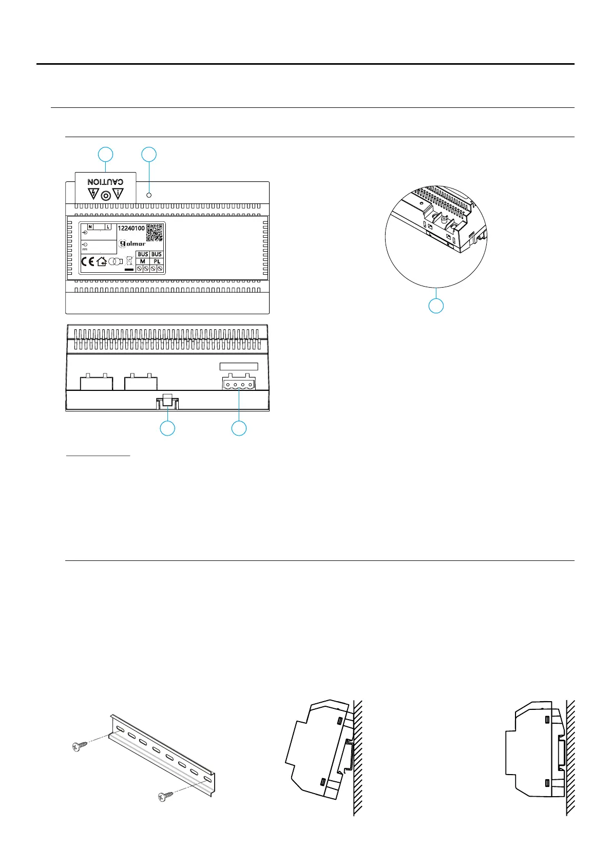
A. On/off indicator light.
B. Protective cover for the current input.
C. Detail of current input terminals without protective
cover.
D. Fastening tab on DIN rail.
E. Installation terminals.
B A
ED
BUS(M) BUS PL( )
C
12240100
OUTPUT
N
L
GOLMAR S.A. C/ Silici, 13 08940 - SPAIN
MADE IN CHINA
BUS 30V 2V 1. A±
0.8A 50-60Hz
5
INPUT ~100-240V
FA-G2+
PL
BUS BUS
V02
Input Voltage:
Input Frequency:
Rated Output Voltage:
Rated Output Current:
Working Temperature:
Dimensions:
100~240Vca
50~60 Hz
0 Vdc3
± 2V
A1,5
-10ºC ~ 40ºC
140*90*60mm
Specification
SOUL/ACCESS DOOR PANEL
 Loading...