6
Instal al tion
The door panel has been designed to withstand diverse environmental conditions. It is however advisable to take
extra precautions to prolong its service life, such as locating it in a covered area.
For optimum image quality, avoid direct contact from light sources (sunshine, street lights, etc.).
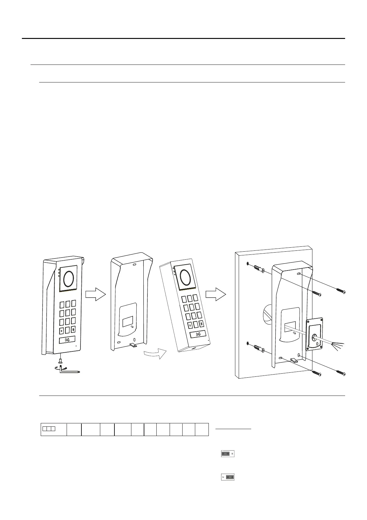
For correct installation: (locate the top of the door panel at a height of 1.65m).
1. Remove the rain shield of the door panel by loosening the bottom screw with theAllen key supplied.
2. Present the to the wall, positioning the top at 1.65m.rain shield
3. (A), as indicated in the drawing.Drill three 6mm holes at the indicated points Insert the plugs supplied and fix the
door panel to the wall using the screws supplied.
4. Pass the installation cables through the cable gland seal (sealing gasket).
5 n the cables to the removable wiring connectors following the installation diagrams.. Con ect
6 efore replacing and closing the door panel, make the adjustments indicatedB on the installation manual
(programming of access code, adjusting the audio level, ...). Make sure that the cable gland seal (sealing
gasket) of the door panel is correctly positioned, indicated point (B) as indicated in the drawing.,
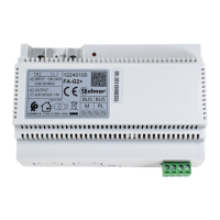
Installation terminals and JP1 jumper
For ease of installation, the installation terminals are removable and supplied in a separate bag. Once the terminals
are wired, place them in position.
BUS BUS, : communications bus (non-polarised).
CV CV-, +: lock release output 12Vdc (maximum 270mA).
AP AP+, -: remote activation button connection. Note: For
correct operation, the monitor's address 1 must be
connected to the Bus.
GND CCTV, : input for external analogue camera.
C , :OM O/NCN potential-free relay output (maximum 6A/24V).
3
2
1
6
5
4
9
8
7
0
1
2
3
4
5
6
7
8
9
0
( )A
(A)
( )A
( )A
( )B
COM
NO/NC G
ND
CCTV AP-
AP+
CV+ CV-
BUS BUS
NO
JUMPER
1 2
NO/NC
NC
3
JP1 jumper: allows the potential free relay
output to be selected as normally open (NO) or
normally closed (NC).
1 2 3
Jumper placed between 1 and 2, sets the
relay output as normally open (NO).
1 2 3
Jumper placed between 2 and 3, sets the
relay output as normally closed.
1
( )
Factory default.
JP1
1
( )
SOUL/ACCESS DOOR PANEL
SOUL/ACCESS DOOR PANEL
 Loading...