2
SAFETY PRECAUTIONS
- Video door entry system with simplified wiring (non-polarised 2-wire bus).
- 1 access panel per installation.
- Up to 3 monitors and apartments with a monitor per installation.2 ART 7/G2+
-
(FA-ART 7W ).power supply unit required for apartment
Up to 3 monitors and apartments with a monitor per installation2 ART 7W/G2+ . Only the master
monitor canactivate Wi-Fi transmission
- Up to i l in8 monitors n paral el (
1 output (to monitor) of the distributor).
- Up to monitors in parallel (installation without distributors) per installation.12
- Up to 3 monitors and apartments with a monitor per installation.2 ART 4/G2+
- Up to 4 monitors per apartment.
- G2Video module EL632 + P/T with pan and tilt mechanism to adjust the telecamera position.
- Up to 8 monitors/ apartments with push button "HZ" activated at the same time (with system and monitors
in standby).
-
Call confirmation tone.
- Visual signals on the door panel for people with impaired hearing (indicating call process,
communication, door open and channel busy).
- Audible signals on the door panel for people with impaired vision (indicating call in progress, missed
call, door open call finished).and
- from monitor (up to 10 seconds), see corresponding monitor user manual.Door opening timeable
- Relay 1 output to activate the DC or AC lock releases actuated by relay.and relay 2
- Always disconnect the power supplybefore installing or making modifications to the devices.
wDo not overtighten the screws on the connector.
- The wiring must run at least 40 cm away from any other wiring.
wTo prevent electric shock, do not remove the cover or handle the wiring connected to the terminals.
wTo avoid damage, the power supply unit must be firmly secured in place.
wEnsure that the air vents are free from obstruction so that air can circulate freely.
- The fitting and handling of these devices must be carried out by authorised personnel.
- On the power supply unit (FA-G2 ):+
wInstall the power supply unit in a dry and protected place free from the risk of water leaks or sprays.
wAvoid locations that are humid, dusty or near heat sources.
CHARACTERISTICS
*
( )
3
INSTALLATION OF THE DOOR PANEL
*
( )
For more information, see the “T632 G2 P/T (code 5012 )” user manual.+ 2528
https://doc.golmar.es/search/manual/50122528
*
( )
NEXA MODULAR G2 VIDEO DOOR ENTRY SYSTEM - BUILDING+
1650
1850
1450
1
N V SCE 90C
99
132,5
56,5
M dul so e
Model
W
H
(width)
(height)
D (depth)
2
CEV90CN
99
2
56
38
3
CEV90
99 mm.
328 mm.
56 mm.
Embedding box dimensions:
*
( )
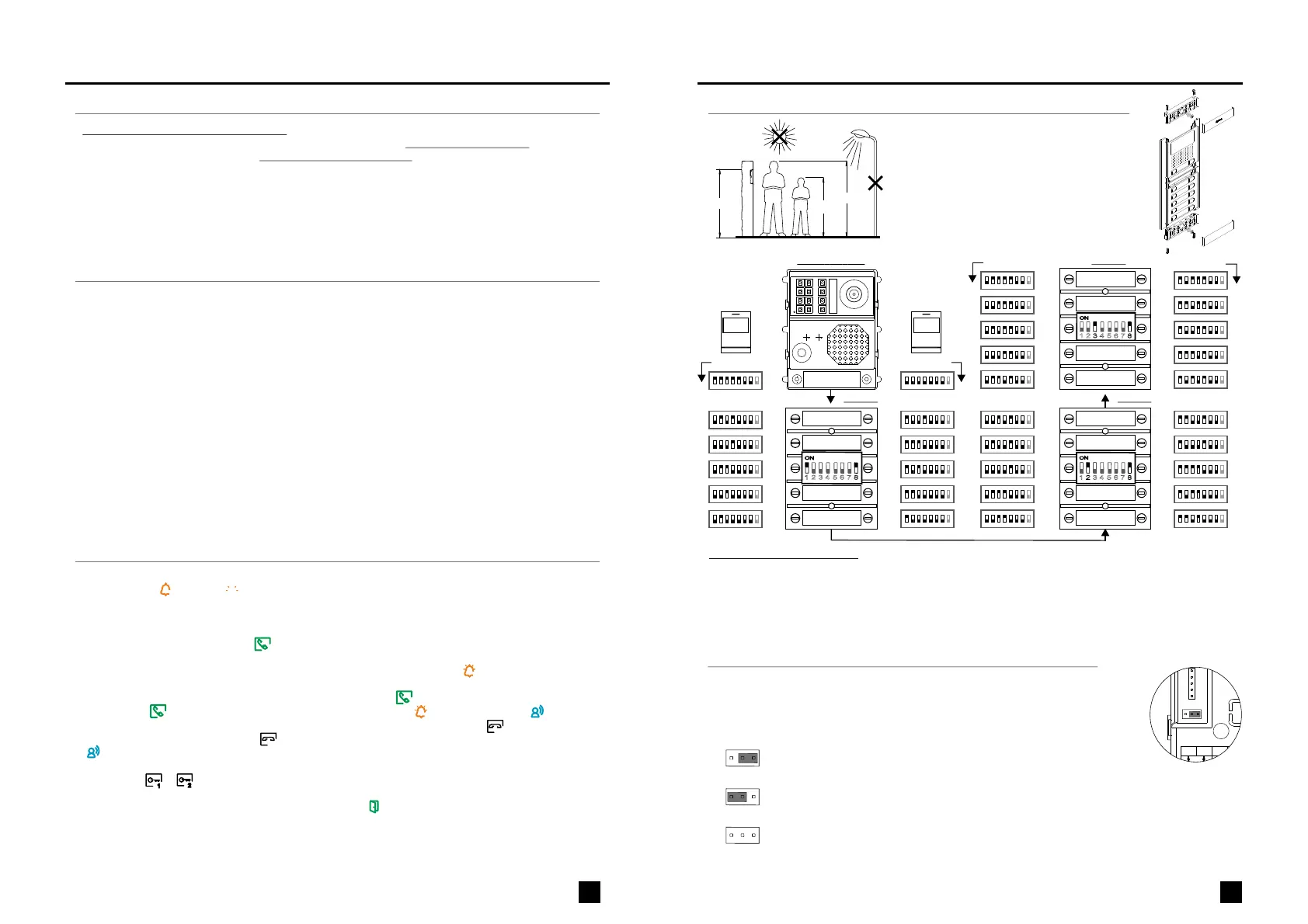
Description and settings:
ENEN
NEXA MODULAR G2 VIDEO DOOR ENTRY SYSTEM - BUILDING+
SYSTEM OPERATION
*
( )
- Connection will last for 90 seconds or until on-the-hook iconis pressed the button below of the ART 4/ ART 7
monitor or of the ART 7W monitoris pressed on-the-hook icon . When communication ends, LEDon the screen
will turn off and the system will become free. If vocal synthesis is enabled, a 'Communication is finished'
message will indicate that the call is over.
- the corresponding monitor .Detailed operation of the monitorand configuration , see user manual
- Upon receiving the call, the image will appear on the screen of the master monitor (and slave 1, if it exists)
without the visitor knowing and icon displayed on the screen will blink green. To view the image from slave
monitors 2 or 3, press the screenpress on one of the buttons of the ART 4/ ART 7 monitor or of the ART 7W
monitor for the image to appear. If the call is not answered within 45 seconds, LED will turn off and the system
will become free.
-
To make a call, the visitor must press the button of the apartment; an audible sound indicates that the call is being
made and LED will turn on. If vocal synthesis is enabled, a 'Call is in progress' message appears indicating
that a call is being made. At this moment, the apartment's monitors receive the call. If another apartment is
called by mistake, press the button for the correct apartment and the first call will be cancelled.
- To establish communication, press off-
the-hook icon on the screen . Door panel LED will .
press the button below off-the-hook icon of the ART 4 / ART 7 monitor or
of theART 7W monitor will turn off and the led turn on
- ,
press the corresponding icon during the call or communication processes:
one press will activate the lock release for seconds and LED will also turn on for seconds. If vocal synthesis
is enabled, a 'Door open' message will be indicated on the door panel.
To open door of the door panelor press the corresponding button below of the ART 4 /ART 7 monitor or
on the screen of the ART 7W monitor
3 3
is
1
2
*
( )
For more information, see the “T632 G2 P/T (code 5012 )” user manual.+ 2528
https://doc.golmar.es/search/manual/50122528
EL610D
EL610D
EL610D
Code Monitor Code Monitor
Code Monitor Code Monitor
1 8
2 3 4 5 6 7
ON
1 3 4 5 6 7
2 8
ON
1 2 4 5 6 7
3 8
ON
C. 13
C. 02
C. 04
C. 06
C. 08
C. 10
C. 10
C. 09
C. 07
C. 05
C. 03
C. 32
C. 12
C. 14
C. 16
C. 18
C. 20
C. 11
C. 19
C. 17
C. 15
C. 13
C. 22
C. 24
C. 26
C. 28
C. 30
C. 12
C. 29
C. 27
C. 25
C. 23
EL632 G2 P/T/ +
1 2 3
ON DIP
4 5 6 7 8
1 2 3
ON DIP
4 5 6 7 8
1 2 3
ON DIP
4 5 6 7 8
1 2 3
ON DIP
4 5 6 7 8
1 2 3
ON DIP
4 5 6 7 8
1 2 3
ON DIP
4 5 6 7 8 1 2 3
ON DIP
4 5 6 7 8
1 2 3
ON DIP
4 5 6 7 8
1 2 3
ON DIP
4 5 6 7 8
1 2 3
ON DIP
4 5 6 7 8
1 2 3
ON DIP
4 5 6 7 8
1 2 3
ON DIP
4 5 6 7 8
1 2 3
ON DIP
4 5 6 7 8
1 2 3
ON DIP
4 5 6 7 8
1 2 3
ON DIP
4 5 6 7 8
1 2 3
ON DIP
4 5 6 7 8
1 2 3
ON DIP
4 5 6 7 8
1 2 3
ON DIP
4 5 6 7 8
1 2 3
ON DIP
4 5 6 7 8
1 2 3
ON DIP
4 5 6 7 8
1 2 3
ON DIP
4 5 6 7 8
1 2 3
ON DIP
4 5 6 7 8
1 2 3
ON DIP
4 5 6 7 8
1 2 3
ON DIP
4 5 6 7 8
1 2 3
ON DIP
4 5 6 7 8
1 2 3
ON DIP
4 5 6 7 8
1 2 3
ON DIP
4 5 6 7 8
1 2 3
ON DIP
4 5 6 7 8
1 2 3
ON DIP
4 5 6 7 8
1 2 3
ON DIP
4 5 6 7 8
1 2 3
ON DIP
4 5 6 7 8
1 2 3
ON DIP
4 5 6 7 8
ART 4/G2+ ART 4/G2+
Audio level jumper description (vocal synthesis and tones mode):
*
( )
Factory default.
The jumper for volume control, allows to select between a minimum, maximum
or mute of the vocal synthesis and tones mode from door panel.the
The jumper for volume control is locate
.
d on the left side of the back of the
module
1 2 3
1
( )
Jumper placed between 2 and 3, set to minimum volume the vocal synthesis
and tones from the door panel.
1 2 3
Jumper placed between 1 and 2 set to maximum volume the vocal synthesis
and tones from the door panel.
,
1 2 3
Jumper removed, set to mute volume the vocal synthesis and tones from the door panel.
1
( )
1
( )
- Ajusting telecamera ( .
pan and tilt mechanism)
- Selecting vocal synthesis language (factory default: Spain) & P1 and P2 ext. button description.
- Description of the module DIP switch:video EL632 G2+ P/T
- Description of the visuals signals on the door panel.
-
Description of the door panel lighting LEDs for low light conditions( ).
- Description of the ( l).vocal synthesis audible signals on the door pane
 Loading...