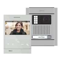
Kit de una vivienda y abrepuertas de continua Golmar.: (K N5110/ ART 4 LITE 1P)IT
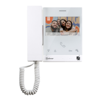
Kit de vivienda (K N5 0 ) y abrepuertasuna : 11 / ART 4 LITE 1P , 1 monitor adicional ART 4 LITEIT
de continua Golmar.
Distancias y Secciones:
4
KIT VIDEOPORTERO G2 NEXA - CHALET+ ART 4 LITE
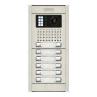
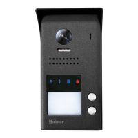
Placa de acceso
VIVIENDA 1
Para abrepuertas de alterna o un 2º abrepuertas ver manual “TKIT632 (cód. 50122 )”.ART 4 LITE 635
https://doc.golmar.es/search/manual/50122635
VIVIENDA 1
4
( )
Kit Videoportero G2 Nexa+ Art 4 Lite
Cód. 5012Web 2635 TKIT632 ART 4 LITE ES GR REV.0121
Golmar se reserva el derecho a cualquier modificación sin previo aviso.
Golmar se réserve le droit de toute modification sans préavis .
Golmar reserves the right to make any modifications without prior notice.
GUÍA RÁPIDA
golmar@golmar.es www.golmar.es
Sistemas de comunicación S.A.
50122816
Instalación 2 hilos sin polarizar
TE NOLOGC IA
Abrepuertas
máx. 12 Vcc/270mA.
AP
( )4
NA2
+
AP-
C1
NA1
AP+
C2
AP+
GND
BUSBUS
Relé 2
Relé 1
_
12Vdc
NC2
CCTV
1 2 3 4 5 6 7 8 910
ON
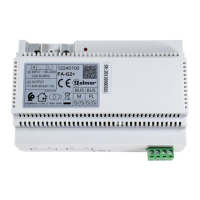
Red
100~240Vac
FA-G2+
LN
BUS(PL)BUS (M)
2
( )
ART 4LITE
A
B
C
ART 4 LITE
FA- 2+G
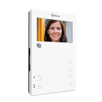
MONITOR PRINCIPAL
ART 4 LITE/G2+
BUS BUS
Cable manguera
RAP-GTWIN/HF 2x1mm
ON
1 2 3 4 5 6 7
8
Red
100~240Vac
FA-G2+
LN
BUS(PL)BUS (M)
2
( )
*
( )
FA-G2+ con corriente de salida: 1,5A.
2
( )
1
( )
ART 4 LITE
Para definir el monitor como principal o secundario, configure el código especial correspondiente: "0550" Principal (valor de
fábrica), ”0551" Secundario1 (ver manual “TKIT632ART 4 LITE”). Cada viviendadebe tenerunmonitor principal y solouno.
Placa de acceso
Abrepuertas
máx. 12 Vcc/270mA.
AP
NA2
+
AP-
C1
NA1
AP+
C2
AP+
GND
BUSBUS
Relé 2
Relé 1
_
12Vdc
NC2
CCTV
1 2 3 4 5 6 7 8 910
ON
B
150m
C
15m
A
80m
A
B
C
FA- 2G +
Configure los microinterruptores del monitor
y la placa tal como se muestra en el esquema
de instalación para vivienda.1
1
( )
CÓDIGO 128
MONITOR PRINCIPAL
ART 4 LITE/G2+
BUS BUS
ON
1 2 3 4 5 6 7
8
CÓDIGO 128
*
( )
Configurar final de línea en el último
monitor. Dip8 a On.
( )4
( )4
( )4
1
( )
MONITOR SECUNDARIO 1
ART 4 LITE/G2+
BUS BUS
ON
1 2 3 4 5 6 7
8
CÓDIGO 128
1
( )
*
( )
Vivienda 1
Cód. 128
A B
80m 150m
Cable manguera
C
15m
RAP-GTWIN/HF 2x1mm
2
Distancias y Secciones:
*
( )
FA-G2+ con corriente de salida: 1,5A.
2
( )
1
( )
Configure los microinterruptores del monitor y la
placa tal como se muestra en el esquema de
instalación para vivienda1 conmonitor adicional.
Configurar final de línea en el último
monitor. Dip8 a On.
1
( )
1
( )
Vivienda 1
Cód. 128
Para abrepuertas de alterna o un 2º abrepuertas ver manual “TKIT632 (cód. 50122 )”.ART 4 LITE 635
https://doc.golmar.es/search/manual/50122635
4
( )
3
( )
3
( )
2
ES ES