Do you have a question about the golmar Plus Nexa and is the answer not in the manual?
Key guidelines and precautions to follow before starting the installation process.
Critical safety measures for handling electrical equipment and installation environment.
Summary of the door entry system's capabilities and supported configurations.
Notices and requirements relevant to the Uno system configuration.
How the system functions during calls, communication, and door release sequences.
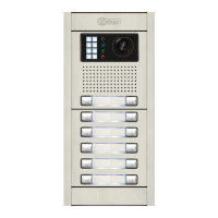
Identification of main door panel parts, modules, and connection cables.
Detailed description of the sound module's front and back sides and components.
Explanation of the purpose and connection for each terminal on the sound module.
Description of the EL610D module, including its connectors and dip switches.
Instructions for correctly placing the embedding box within the wall structure.
Steps to modify the embedding box for cable passage and entry.
Procedure for passing wires through and fixing the embedding box.
Instructions for inserting and securing electronic modules into the door panel frame.
Method for attaching the door panel frame to the embedding box.
Wiring instructions for connecting push button modules using short cables.
Using the RAP-610D cable for connecting push buttons between modules.
Setting call codes for push buttons using the EL610D module's dip switches.
Details on the Bus Nexa connector and its compatibility with other modules.
Procedure for connecting EL3002 illumination modules using the Bus Nexa connection.
Explanation of the illumination LEDs on the door panel during calls.
Description of LED signals indicating call status, communication, and door release.
Guide to SW1 dip switch placement and its impact on system operation.
Using SW1 for modes like EL500/EL501, cable type, and system resistors.
Guide to SW2 dip switch placement and its impact on system operation.
Using SW2 for programming, master/slave, and setting building codes.
Method for calculating building codes using binary values on SW2.
Introduction to the different programming modes for the general door panel.
Steps to assign monitors/telephones to buttons using a direct call method.
Method for programming push buttons with specific backbone codes using SW2.
Method for programming push buttons with monitor/telephone codes using SW2.
Procedure to associate monitors/telephones with general door panel push buttons.
Details of the CN3 connector's location, functions, and terminal assignments.
Steps for fine-tuning audio levels and aiming the telecamera.
Final steps to close the frame and insert labels into the door panel.
Guidelines for assembling door panels with one or multiple modules.
Instructions for fixing the door panel and its closing elements.
Detailed installation guide and safety measures for power supplies.
Procedures for installing lock releases, including important notes on varistors.
Diagram showing distributor wiring and power supply connections to the door panel.
Diagram and instructions for connecting a video door entry system with coaxial cable.
Technical data for RG-59 coaxial cables used in video installations.
Schematics for connecting D6L-Plus/2H and EL562 distributors in the system.
Diagram and instructions for connecting a video system with twisted pair cable.
Critical SW1 dip switch setting for video installations using twisted pair.
Diagram illustrating the wiring of T-540 Plus SE telephones.
Schematic for connecting audio door entry systems and components.
Table specifying required cable cross-sections for audio connections.
Diagrams for connecting inner door panels to monitors within different backbones.
Diagrams for connecting general door panels to monitors within different backbones.
Diagram for connecting inner door panels to monitors in Backbone 2.
Diagram for connecting general door panels to monitors in Backbone 0.
Diagram for video systems with general door panels in large residential complexes.
Key considerations and distributor usage for large complex video system installations.
Details on cable types and connections for video systems in large complexes.
Diagram for audio systems with general door panels in large residential complexes.
Important notes and cable specifications for audio systems in large complexes.
Procedure for wiring an AC lock release using a TF-104 transformer.
Instructions for connecting multiple power supplies to expand system capacity.
Method for activating the lock release using an external push button.
Wiring diagram and instructions for the FDI voice synthesis module.
Steps to diagnose and resolve issues when the system is not operating.
Solutions for audio level issues, feedback, and call reception problems.
Fixes for lack of video image, door open function, and push button issues.
Confirmation of product compliance with EU Electrical Safety and EMC directives.
Conditions for device operation and the manufacturer's right to make modifications.
| Brand | golmar |
|---|---|
| Model | Plus Nexa |
| Category | Intercom System |
| Language | English |