95
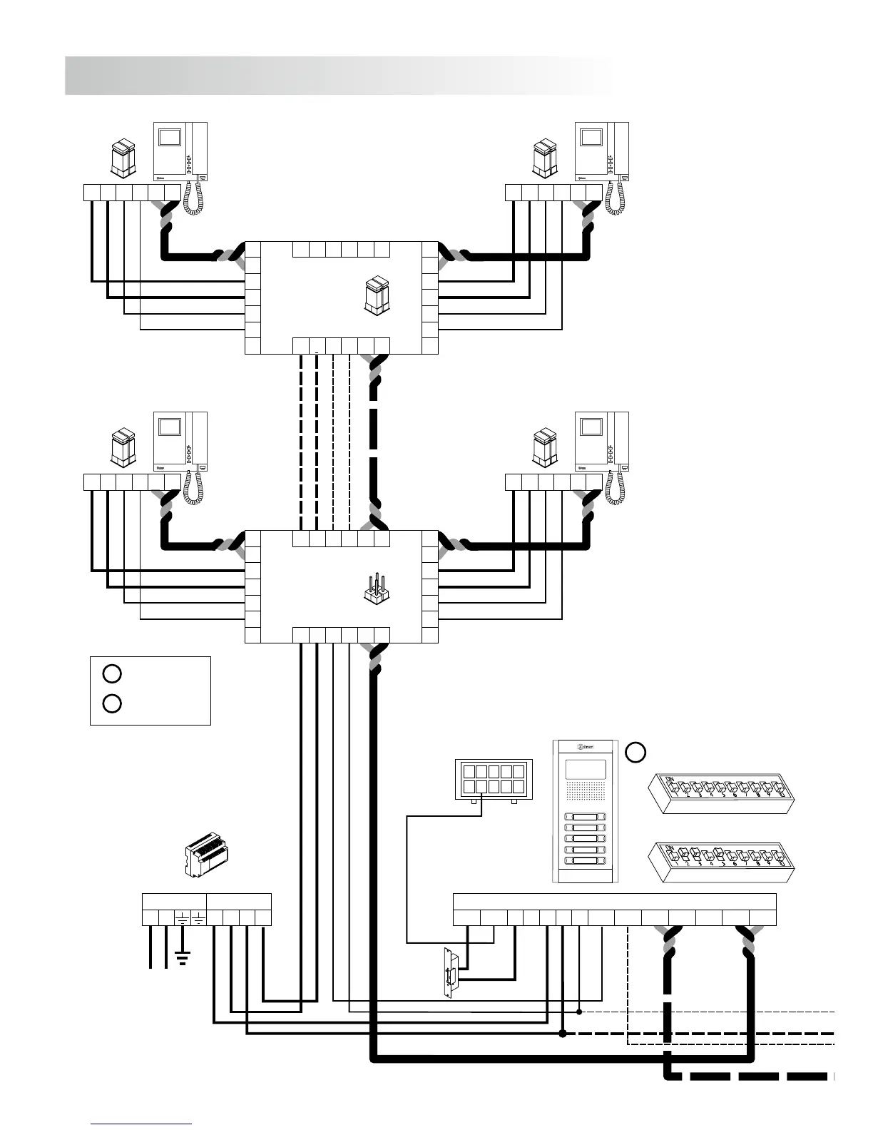
INSTALLATION DIAGRAMS
FA-Plus/C o FA-Plus
SEC
PRI
~~
+ +
--
JP1
A
A
D
D
CT
+
+
V
pi
V
d1
M
pi
M
d1
_
_
A
D
CT
+
V
d6
M
d6
_
A D+
V
po
M
po
_
D6L-Plus/2H
V
p
M
p
A D
_
+
EL562
JP1
V
p
M
p
A D
_
+
EL562
JP1
JP1
A
A
D
D
CT
+
+
V
pi
V
d1
M
pi
M
d1
_
_
A
D
CT
+
V
d6
M
d6
_
A D+
V
po
M
po
_
D6L-Plus/2H
V
p
M
p
A D
_
+
EL562
JP1
V
p
M
p
A D
_
+
EL562
JP1
D
Malla
Vin-AinAout Vin+ Vout-Vout+
CN1
+
-
+CV1CV2
-
10
1
9
2
8
3
7
4
6
5
CN3
* Place this power supply
as closest as possible
to the first distributor.
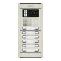
Access door panel
M =Master.
S =Slave.
Lock release
Vd.c.
M
SW1
SW2
96
ONE OR SEVERAL ACCESSES DOORS
FA-Plus/C
SEC
PRI
230110 0
--
+ + D
Malla
Vin-AinAout Vin+ Vout-Vout+
CN1
+
-
+CV1CV2
-
10
1
9
2
8
3
7
4
6
5
CN3
Main Main
* Take off JP1 jumper
of all the distributors
except in the last one.
1,00mm² 2,50mm²
0,25mm² 0,25mm²
CAT-5 CAT-5
Terminal
SECTIONS CHART
50m.
Distance
150m.
A , A , A, D
in out
V , V , V , M
in+,- out+,- p,d p,d
+, , CV1, CV2–
v
ideo installation without coaxial cable.
Lock release
Vd.c.
Access door panel
The installation diagram shows the connection of a video system with one or several door panels for
the same building.
If the system has one access door panel only, override the wiring to the second door panel.
If the system has more than one access door panel, wire the second panel as shown on the diagram.
In case of more than two door panels, wire them as the second is connected.
IMPORTANT: For this type of installation, the door panels must have configured the switch nº.3 of
the SW1 configuration dip-switch to ON (page 85)in each and the monitors must
have an EL562 plugged in each (see page 74 for manual web link or QR in box
monitor).
SW1
SW2
S