97
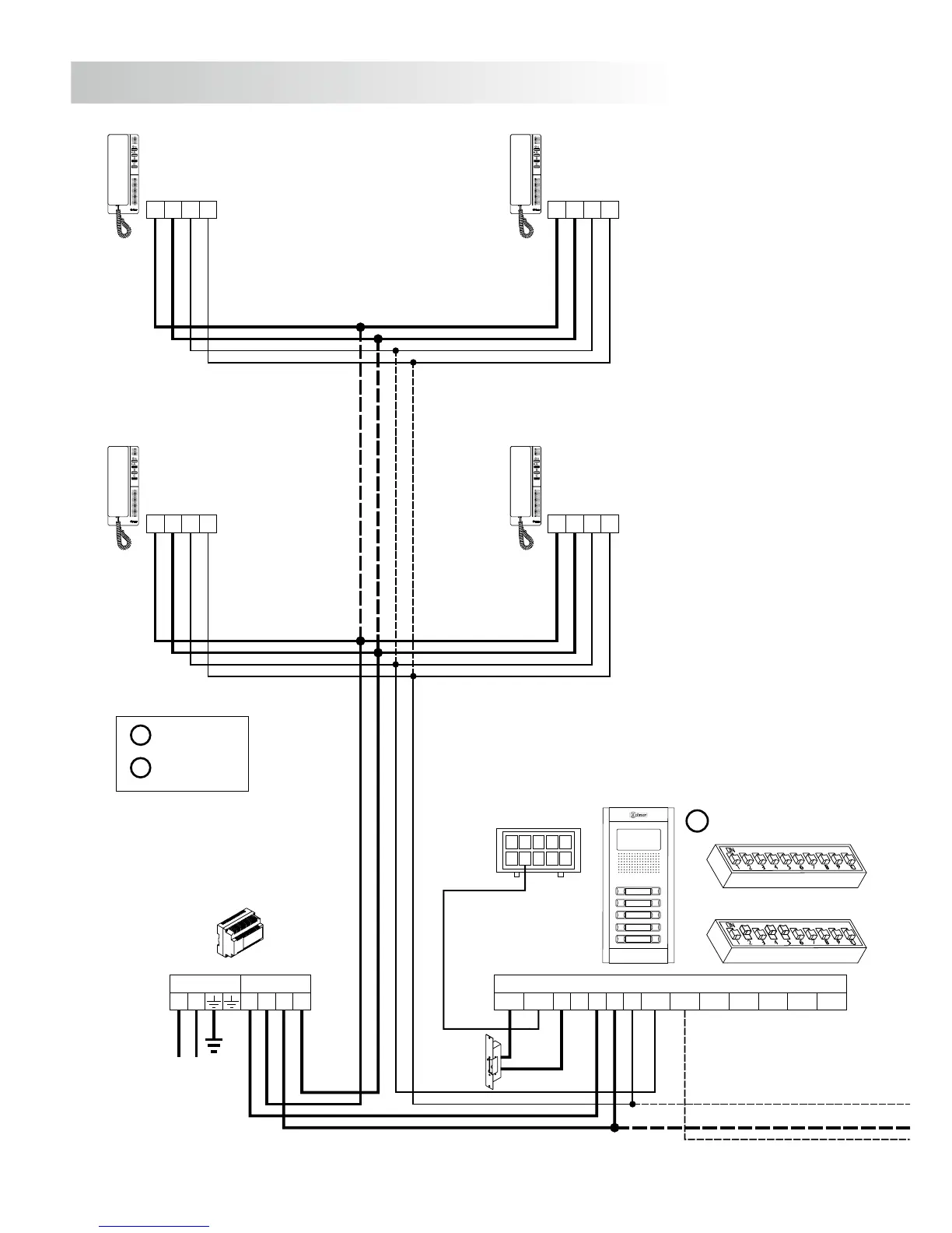
INSTALLATION DIAGRAMS
FA-Plus/C o FA-Plus
SEC
PRI
~~
+ +
--
A
A
+
+
_
_
D
D
D
Malla
Vin-AinAout Vin+ Vout-Vout+
CN1
+
-
+CV1CV2
-
10
1
9
2
8
3
7
4
6
5
CN3
Main
*Place this power supply
as closest as possible
to the first telephone.
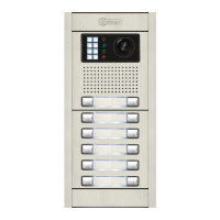
Access door panel
M =Master.
S =Slave.
Lock release
Vd.c.
A
+
_
D
A
+
_
D
M
SW1
SW2
98
ONE OR SEVERAL ACCESSES DOORS
D
Malla
Vin-AinAout Vin+ Vout-Vout+
CN1
+
-
+CV1CV2
-
10
1
9
2
8
3
7
4
6
5
CN3
FA-Plus/C
SEC
PRI
230
--
110 0
+ +
Main
A
udio installation.
1,00mm² 2,50mm²
0,25mm² 0,25mm²
Terminal
SECTIONS CHART
50m.
Distance
150m.
A , A , A, D
in out
+, , CV1, CV2–
Lock release
Vd.c.
Access door panel
The installation diagram shows the connection of an audio system with one or several door panels
for the same building.
If the system has one access door panel only, override the wiring to the second door panel.
If the system has more than one access door panel, wire the second panel as shown on the diagram.
In case of more than two door panels, wire them as the second is connected.
SW1
SW2
S
T-540 Plus SE T-540 Plus SE
T-540 Plus SE T-540 Plus SE