12
4 Preparation
>> Comparethespecicationsofalluseddevicestoensurecom
patibility.
>> Check the scope of delivery for completeness and integrity.
5 Installation
The surface must be stable. The supplied mounting material is only for
concrete and stone walls. For mounting on other surfaces, other dowels must
be used.
Plants, street lighting, reecting surfaces and arbitrarily moving objects may
not be located in the detection area. Recommended mounting location: as
sunny as possible, 3-4 m mounting height.
1. Usetheallenkey(9)tolossenthescrewxing(6)ofthebracket.
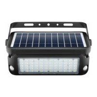
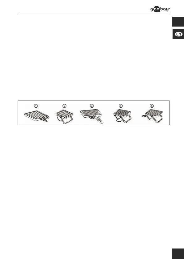
2. Carefully unfolding the bracket and the LED light (1) as shown in Fig. 5.
Fig. 5 : Unfolding the LED solar wall
3. Adjustthedesiredangleofinclinationandtightenthescrewxing
again.
4. Draw 2 mounting holes on the wall at the distance of the mounting
lugs (4).
5. If necessary, use a spirit level for marking.
6. Drill 2 mounting holes with a Ø 8 mm drill.
7. Insertthexingscrewswiththemetaldowels(8)intothedrilling
hole.
Leave the screw heads about 4 mm out of the wall.
8. Hang the product on the mounting lugs (4) of the bracket onto the
xingscrews.
9. Hold the LED solar wall light with the other hand.
10. Gentlytightenthexingscrews.
6 Operating
The range can not be adjusted.
It can be varied due to the mounting height and angle of inclination.
The switch-off delay cannot be set.
The trigger sensitivity cannot be adjusted.
1. Switch on the LED solar wall light via the control panel (7). See Fig.
6 and table 4.
2. Select the desired mode:
 Loading...