EasyManua.ls Logo

Goodman AVPTC42D14 series User Manual

Goodman AVPTC42D14 series
32 pages
To Next Page IconTo Next Page
Page #1 background imageLoading...
Page #1 background image
AVPTC**14**
© 2013-2014 Goodman Manufacturing Company, L.P.
5151 San Felipe, Suite 500, Houston, TX 77056
www.goodmanmfg.com - or - www.amana-hac.com
P/N: IO-443E Date: October 2014
AIR HANDLERS
INSTALLATION & OPERATING INSTRUCTIONS
®
is a registed trademark of Maytag Corporation or its related companies and is used under license. All rights reserved.
Contents
1 Important Safety Instructions ................................... 2
2 Shipping Inspection .................................................. 2
3 Codes & Regulations................................................. 3
4 Replacement Parts .................................................... 3
5 Pre-Installation Considerations................................ 3
6 Installation Location .................................................. 4
7 Refrigerant Lines ....................................................... 7
8 Condensate Drain Lines............................................ 7
9 Ductwork .................................................................... 8
10 Return Air Filters ....................................................... 8
11 Electric Heat ............................................................... 9
12 Electrical and Control Wiring.................................. 10
13 Achieving 2% Low Leakage Rate ........................... 11
14 24 Volt Wiring ........................................................... 11
15 Auxiliary Alarm Switch ............................................ 13
16 AVPTC Motor Orientation........................................ 13
17 Circulator Blower..................................................... 14
18 Heat Kit Selection .................................................... 16
19 Troubleshooting....................................................... 16
20 ComfortNet™ System.............................................. 18
21 Start-Up Procedure .................................................. 20
22 Regular Maintenance............................................... 20
23 Communications Troubleshooting Chart .............. 23
24 Air Handler Advanced Features Menu ................... 24
25 Troubleshooting....................................................... 25
27 Wiring Diagrams ...................................................... 29
26 Diagnostic Codes .................................................... 32
ATTENTION INSTALLING PERSONNEL
Prior to installation, thoroughly familiarize yourself with this Instal-
lation Manual. Observe all safety warnings. During installation or
repair, caution is to be observed. It is your responsibility to install
the product safely and to educate the customer on its safe use.
RECOGNIZE THIS SYMBOL AS A
SAFETY PRECAUTION.
Question and Answer IconNeed help?

Do you have a question about the Goodman AVPTC42D14 series and is the answer not in the manual?
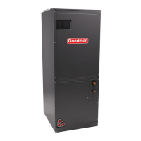
Goodman AVPTC42D14 series Specifications

General IconGeneral
ModelAVPTC42D14 series
Cooling Capacity3.5 Ton
RefrigerantR-410A
Nominal Airflow1400 CFM
Voltage208-230 V
Phase1
Cabinet TypeFoil-faced Insulation
Width21 inches
Depth21 inches
TypeAir Handler
CFM1400 CFM
Maximum External Static Pressure0.5 in. w.c.
Heating Capacity42, 000 BTU/h

Summary

Important Safety Instructions

General Safety Warnings

Key safety precautions including high voltage, proper installation, and avoiding hazardous materials.

Shipping Inspection

Parts, Handling, and Codes

Inspect unit for parts, follow handling guidelines, and adhere to codes and regulations.

Replacement Parts

Pre-Installation Considerations

Preparation and System Setup

Ensure readiness with proper preparation, system matching, tubing, and clearance requirements.

Installation Location

Upflow Installation

Instructions for upflow orientation, including drip shield removal and drain connections.

Horizontal Left Installation

Details for horizontal left orientation, including primary and secondary drain connections.

Downflow/Horizontal Right Installation

Procedure for downflow/horizontal right installation, requiring a downflow kit.

Refrigerant Lines

Tubing Sizing and Preparation

Selecting tubing size and preparing ends for leak-free refrigerant line connections.

TXV Model Tubing Connections

Step-by-step instructions for connecting refrigerant lines on TXV models.

Condensate Drain Lines

Ductwork Requirements

Requirements for supply and return ductwork, including sizing and sealing.

Ductwork

Return Air Filters

Electric Heat

Electrical and Control Wiring

Service Inspection, Wire Sizing, and Protection

Perform inspection, select wire size, and ensure proper overcurrent protection.

Supply Voltage Connections

Details on making supply voltage connections through knockouts using copper conductors.

Achieving 2% Low Leakage Rate

24 Volt Wiring

Thermostat and Dehumidistat Connections

Connecting thermostat and dehumidistat wires to the integrated control module.

Auxiliary Alarm Switch

AVPTC Motor Orientation

Circulator Blower and Electric Heat Airflow

Blower Speed and Airflow Adjustment

Adjusting blower speed and airflow using DIP switches for cooling and fan-only modes.

Electric Heating Airflow Settings

Setting electric heating airflow using DIP switches based on heater kit kW rating.

Heat Kit Selection

Troubleshooting

ESD Precautions and Diagnostics

Protecting components from ESD and using diagnostic charts for troubleshooting.

ComfortNet™™ System

System Overview and Wiring

Understanding ComfortNet system communication, wiring, and thermostat connections.

Advanced Features, Diagnostics, and Troubleshooting

Accessing advanced features, diagnostics, and troubleshooting for the ComfortNet system.

Start-Up Procedure

Regular Maintenance

Communications Troubleshooting Chart

Air Handler Advanced Features Menu

Menu Navigation and Settings

Accessing and configuring advanced features, diagnostics, and system status.

Diagnostics and Identification

Viewing fault history, model, serial number, and software revision.

Troubleshooting

Abnormal Operation Symptoms and Codes

Identifying operational issues based on LED codes, thermostat messages, and diagnostic charts.

System Faults and Communication Errors

Diagnosing system faults related to power, network communication, and data errors.

Circulator Blower Motor Issues

Troubleshooting blower motor run, communication, mismatch, limits, and trip faults.

Blower Motor Voltage and Airflow Problems

Addressing motor voltage issues, parameter errors, and low airflow conditions.

Wiring Diagrams

General Wiring Diagrams

Electrical connection diagrams for the air handler and integrated control module.

3-Phase Heat Kit Wiring

Wiring diagram specific to the installation of a 3-phase heat kit.

SPLIT SYSTEMS Maintenance

Filter and Motor Care

Guidance on filter replacement, compressor, and fan motor maintenance.

Outdoor Unit Maintenance and Servicer Checks

Cleaning outdoor coils and performing pre-servicer checks for troubleshooting.

Diagnostic Codes

Related product manuals