EasyManua.ls Logo

Goodman CONDENSING UNIT - User Manual

Goodman CONDENSING UNIT
24 pages
Print Icon
To Next Page IconTo Next Page
Loading...
CONDENSING UNIT
SINGLE / THREE PHASE HEAT PUMPS
INSTALLATION & SERVICE REFERENCE
© 2010-2012 Goodman Manufacturing Company, L.P.
5151 San Felipe, Suite 500, Houston, TX 77056
www.goodmanmfg.com -or- www.amana-hac.com
P/N: IO-403D Date: May 2012
NOTICE
THIS UNIT IS SHIPPED WITH A NITROGEN/HELIUM
HOLDING CHARGE ONLY. UNIT MUST BE EVACUATED
AND CHARGED PER INSTALLATION INSTRUCTIONS
WITH REFRIGERANT LISTED ON SERIAL RATING PLATE.
NOTICE
UNITS SHIPPED WITH A HOLDING CHARGE ARE
INTENDED FOR COMPONENT REPLACEMENT ONLY ON
EXISTING SYSTEMS, AND NOT INTENDED FOR USE IN
NEW SYSTEMS OR NEWLY CONSTRUCTED HOMES.
EPA REGULATIONS PROHIBIT THE SALE OR
DISTRIBUTION OF APPLIANCES PRE-CHARGED WITH
THE REFRIGERANT R-22 IF THOSE APPLIANCES ARE
MANUFACTURED AFTER JANUARY 1, 2010.
COMPONENTS OF EXISTING R-22 SYSTEMS MAY BE
REPAIRED AND/OR REPLACED.
NOTICE
UNITS MUST ONLY BE USED AS REPLACEMENT
COMPONENTS FOR PRE-2010 INSTALLED SYSTEMS.
See unit rating plate for initial charge.
Important Safety Instructions
The following symbols and labels are used throughout this
manual to indicate immediate or potential safety hazards. It is
the owner’s and installer’s responsibility to read and comply
with all safety information and instructions accompanying these
symbols. Failure to heed safety information increases the risk
of personal injury, property damage, and/or product damage.
HIGH VOLTAGE!
Disconnect ALL power before servicing.
Multiple power sources may be present.
Failure to do so may cause property damage,
personal injury or death.
WARNING
ONLY individuals meeting (at a minimum) the
requirements of an “Entry Level Technician” as
specified by the
may use this
information. Attempting to install or repair this unit
without such background may result in product
damage, personal injury, or death.
Air-Conditioning, Heating and
Refrigeration Institute (AHRI)
Scroll equipped units should never be used to evacuate
the air conditioning system. Vacuums this low can cause
internal electrical arcing resulting in a damaged or failed
compressor.
CAUTION
Important Note to the Owner Regarding Prod-
uct Warranty
Your warranty certificate is supplied as a separate document
with the unit installed by your contractor. Read the limited
warranty certificate carefully to determine what is and is not
covered and keep the warranty certificate in a safe place. If you
are unable to locate the warranty certificate please contact
your installing contractor or contact customer service (877-
254-4729) to obtain a copy.
Shipping Inspection
Always keep the unit upright; laying the unit on its side or top
may cause equipment damage. Shipping damage, and subse-
quent investigation is the responsibility of the carrier. Verify
the model number, specifications, electrical characteristics,
and accessories are correct prior to installation. The distribu-
tor or manufacturer will not accept claims from dealers for trans-
portation damage or installation of incorrectly shipped units.
Codes & Regulations
This product is designed and manufactured to comply with
national codes. Installation in accordance with such codes and/
or prevailing local codes/regulations is the responsibility of the
installer. The manufacturer assumes no responsibility for equip-
ment installed in violation of any codes or regulations. Rated
performance is achieved after 72 hours of operation.
The United States Environmental Protection Agency (EPA)
has issued various regulations regarding the introduc-
tion and disposal of refrigerants. Failure to follow these
regulations may harm the environment and can lead to
the imposition of substantial fines. Should you have any
questions please contact the local office of the EPA.
If replacing a condensing unit or air handler, the system must
be manufacturer approved and Air Conditioning, Heating and
Refrigeration Institute (AHRI) matched. NOTE: Installation of
unmatched systems is strongly discouraged.
Operating the unit in a structure that is not complete (either as
part of new construction or renovation) will void the warranty.

Questions and Answers

Summary

Important Safety Instructions

High Voltage Warning

Disconnect ALL power before servicing due to high voltage risks.

Technician Qualification Requirements

Specifies minimum technician qualifications for using this manual.

Safe Refrigerant Handling

Refrigerant Health and Safety Hazards

Warns about refrigerant being heavier than air and potential asphyxiation.

Refrigerant Cylinder Safety

Provides safety guidelines for handling refrigerant cylinders to prevent explosion.

Refrigerant Line Connections and Testing

System Evacuation Procedure

Details the steps for evacuating the refrigerant system to remove air and moisture.

Electrical Connections and Safety

High Voltage Electrical Safety

Emphasizes disconnecting all power before electrical servicing.

Three-Phase Compressor and System Startup

Initial System Startup Procedures

Guides on opening service valves correctly to avoid refrigerant loss.

Refrigerant Charge Verification and Adjustment

Refrigerant Charge Precautions

Warns against overcharging or operating the unit in a vacuum.

Cooling Mode Charge Adjustment

Details adjusting refrigerant charge for cooling based on temperature.

Superheat and Subcooling Adjustment Procedures

System Troubleshooting Guide

Troubleshooting Analysis Table

A table correlating symptoms with possible causes, tests, and remedies.

Overview

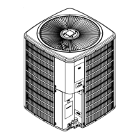
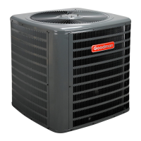
This document describes the Condensing Unit, a single/three-phase heat pump for installation and service. It is designed for outdoor installations and is crucial for both heating and cooling systems.

Function Description:

The Condensing Unit is a key component of a heating and air conditioning system. It operates as a heat pump, capable of both heating and cooling. The unit is shipped with a nitrogen/helium holding charge and must be evacuated and charged with the specified refrigerant (listed on the serial rating plate) according to installation instructions. These units are primarily intended for component replacement in existing systems (pre-2010 installed systems) and are not for use in new systems or newly constructed homes due to EPA regulations regarding R-22 refrigerant.

Important Technical Specifications:

  • Refrigerant: The unit is shipped with a nitrogen/helium holding charge and must be charged with the refrigerant listed on the serial rating plate. EPA regulations prohibit the sale or distribution of R-22 pre-charged appliances manufactured after January 1, 2010.
  • Electrical:
    • High Voltage: Requires disconnection of all power before servicing, as multiple power sources may be present. Wiring must conform to NEC or CEC and all local codes. Undersized wires can lead to poor performance, equipment damage, or fire. Copper conductors are required.
    • Low Voltage: Condensing unit control wiring requires a 24 Volt minimum, 25VA service from the indoor transformer. Wires should be no smaller than 18 AWG.
    • Overcurrent Protection: Approved devices include time delay fuses and HACR type circuit breakers, designed to allow sufficient time for the motor-compressor to start and accelerate its load.
    • Voltage Unbalance: The supply voltage can be unbalanced (phase to phase) within 2%. The formula for calculating percentage voltage unbalance is: Percentage Voltage Unbalance = 100 x (Max. Voltage Deviation From Average Voltage / Average Voltage).
  • Compressor:
    • Scroll Compressors: These are power phase dependent and can rotate in either direction. Proper rotation (suction pressure drops, discharge pressure rises) must be verified. Operating in reverse makes them noisier and reduces current draw.
    • Reciprocating Compressors and Non-Bleed TXVs: These require a hard start kit.
  • Refrigerant Lines:
    • Material: Refrigerant grade (dehydrated and sealed) copper tubing.
    • Insulation: Armflex (or equivalent) with 3/8" min. wall thickness is recommended for suction lines to prevent condensation. 1/2" insulation may be required in hot, high humidity areas.
    • Sizing: Recommended line diameters vary by unit tonnage and line length (e.g., for 1 1/2 to 2 tons, 0-24 ft: 5/8" Suct, 1/4" Liq; 25-49 ft: 3/4" Suct, 3/8" Liq; 50-79 ft: 3/4" Suct, 3/8" Liq). Longer runs (over 79 ft or vertical elevation changes over 50 ft) require consulting the Remote Cooling Service Manual or distributor.
    • Burying Lines: If unavoidable, lines must be insulated separately and enclosed in waterproof material (conduit or pipe) with sealed ends.
  • Installation Clearances:
    • Vertical: Minimum of 60 inches between the top of the unit and any obstruction above.
    • Horizontal: Minimum airflow clearances vary by model type (Residential: A=10", B=10", C=18", AA=20"; Light Commercial: A=12", B=12", C=18", AA=24").
    • Snow/Ice: In areas with heavy snow or prolonged subfreezing temperatures, the unit should be elevated (2 1/2" for +15°F and above, 8" for -5°F to +14°F, 12" for below -5°F) to allow unobstructed drainage and airflow.

Usage Features:

  • Installation: Must be installed by individuals meeting "Entry Level Technician" requirements (AHRI certified). The unit should be placed on a solid, level foundation that will not shift or settle. For rooftop installations, the structure must support the weight, and vibration absorbing pads/springs are recommended.
  • Refrigerant Handling: Safe practices are critical due to refrigerants being heavier than air and potentially causing frostbite or blindness. Never purge refrigerant into enclosed spaces; always reclaim it. Wear gloves and goggles. Never burn refrigerant. Avoid applying flame or steam to cylinders; partially immerse in warm water for faster charging. Do not fill cylinders more than 80% full. Store cylinders in a cool, dry place. Use only returnable service cylinders that are free of damage, have a hydrostatic test date within 5 years, and meet pressure ratings.
  • System Evacuation: Scroll compressors should never be used to evacuate the system, as low vacuums can cause internal electrical arcing. The system must be evacuated to 250 microns or less using a vacuum pump connected to both suction and liquid service valves.
  • Leak Testing: Use dry nitrogen and soapy water. Never use oxygen, high pressure air, or flammable gases. If using a leak detector, charge with 10 psi of appropriate refrigerant, then use nitrogen to working pressure.
  • Charging: Refrigerant must be added after evacuation. For fixed orifice systems, superheat is adjusted by adding/recovering charge. For expansion valve systems, subcooling and superheat are adjusted by turning the TXV valve stem and adding/recovering charge.
  • Compressor Rotation (Three-Phase): Verify proper rotation by checking suction and discharge pressures. If incorrect, switch any two leads at the unit contactor.
  • System Start-up: Open service valves until the stem is 1/8" from the retainer. Do not introduce liquid refrigerant into the compressor crankcase. Allow the system to stabilize for 10-20 minutes before checking charge.
  • Heating Mode Charging: Measure hot gas discharge at the compressor. Adjust charge to maintain a clear sight glass and achieve a hot gas temperature of 105°F + ambient (±5°F).
  • Defrost Control: Uses a Time/Temperature method. Adjustments to defrost timing (30, 60, or 90 minutes) can be made via a jumper on the defrost control board.

Maintenance Features:

  • Routine Checkup: Bi-annual maintenance checkups by a qualified servicer are strongly recommended before heating and cooling seasons.
  • Filter Maintenance: Never operate the unit without a filter. Check filters monthly and clean/replace as required. High-efficiency filters are available.
  • Coil Cleaning: Keep the outdoor coil clean. Dirt, leaves, or debris can restrict airflow. If cleaning is necessary, hire a qualified servicer to avoid damaging the tubing.
  • Compressor/Motor: Compressor motors are hermetically sealed and do not require additional oiling. Indoor and outdoor fan motors are permanently lubricated.
  • Troubleshooting: The manual provides a detailed troubleshooting analysis table covering various complaints (e.g., high/low head pressure, low suction pressure, compressor not starting) and their possible causes and remedies. Common causes for unsatisfactory heat pump operation in heating mode include dirty filters, low return air temperatures, undercharging, poor defrost termination, and reversing valve issues.

Goodman CONDENSING UNIT Specifications

General IconGeneral
BrandGoodman
ModelCONDENSING UNIT
CategoryHeat Pump
LanguageEnglish

Related product manuals