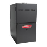
Do you have a question about the Goodman GMES8 U Series and is the answer not in the manual?
Key notices and safety warnings for users and service personnel regarding product operation and maintenance.
Guidance on understanding and interpreting safety symbols, words, and labels used in the manual.
Details the dangers of carbon monoxide poisoning and necessary precautions for enclosed areas.
Instructions on how to shut off the furnace in case of overheating or gas supply failure.
Explanation of the 13-digit model and manufacturing number structure for Goodman furnaces.
Details on identifying Goodman furnace brand, configuration, motor, gas valve, and AFUE rating.
Information on Goodman furnace NOx type, cabinet width, and maximum airflow capacity.
Explanation of the 14-digit model and manufacturing number structure for Amana furnaces.
Details on identifying Amana furnace brand, configuration, motor, gas valve, and AFUE rating.
Information on Amana furnace NOx type, cabinet width, and maximum airflow capacity.
Essential safety warnings and cautions to follow during furnace installation, adjustment, servicing, or operation.
Steps to prevent electrostatic discharge damage to electronic components during furnace service.
Defines the intended use and limitations of the furnace, specifying it's for natural gas only.
Specifies minimum and maximum inlet gas supply pressures required for reliable furnace operation.
Details the 24-volt gas valve operation, manual controls, and pressure measurement points.
Guidelines for gas piping installation, sizing, and leak testing procedures.
Instructions and requirements for operating the furnace at high altitudes, including derating and adjustments.
Safety warnings and guidelines for proper polarization, grounding, and wiring of furnace electrical components.
Explanation of continuous fan operation, speed adjustment, and ductwork airflow requirements.
Describes the step-by-step operational sequence for power up and heating mode.
Details the normal operational sequence for the furnace when operating in cooling mode.
Explains the operational sequence when the furnace fan is operated independently.
Information on unique ID plugs for specific models and procedures for their installation.
Checklist for a qualified technician to inspect furnace components annually for proper working order.
Highlights the importance of filter maintenance and potential issues from dirty filters.
Details on blower motor lubrication, cleaning, and flame sensor maintenance procedures.
Steps to conduct a heating performance test to verify BTU input and airflow against specifications.
Procedure for measuring gas meter dial revolutions to determine furnace gas input rate (CFH).
Formula and example for calculating the furnace's BTU/HR input using gas meter readings and BTU content.
Diagram and list identifying key components of the furnace for servicing purposes.
Procedures for testing furnace electrical voltage, wiring continuity, and connections.
Troubleshooting steps for thermostat and low-voltage wiring issues, including jumper tests.
Procedure for checking the 24-volt transformer and its associated control circuit for proper operation.
Instructions for testing the blower motor, its wiring, and measuring duct static pressure for airflow.
Procedures for measuring air temperature rise and testing the primary limit control for proper operation.
Steps to test auxiliary limit control, induced draft motor, and redundant gas valve for proper function.
Detailed procedure for measuring inlet gas supply pressure using a manometer.
Steps to measure and adjust gas manifold pressure, including regulator adjustments and safety precautions.
Procedures for checking igniter, pressure transducer, and activating the field test mode for diagnostics.
Guidance on control board grounding and testing for delayed ignition issues.
Procedure for checking the flame sensor's micro-amp reading and cleaning it if necessary.
Troubleshooting furnace failures based on LED status codes, fault descriptions, causes, and corrective actions.
Diagnosing continuous inducer blower or circulator blower operation with no furnace output, based on LED codes.
Troubleshooting abnormal noise, ID plug issues, and interpreting various LED status indicators for furnace operation.
Procedures for recalling and clearing stored fault codes from the integrated control module.
Wiring diagram for the control board, showing component connections and labels.
Table detailing LED activity, error codes, and their corresponding fault descriptions and meanings.
| Model | GMES8 |
|---|---|
| Fuel Type | Natural Gas |
| Efficiency Rating | 80% |
| AFUE | 80% |
| Heating Capacity | 40, 000-120, 000 BTU/h |
| Blower Motor | Multi-Speed |
| Blower Motor Type | PSC |
| Heat Exchanger Material | Aluminized Steel |
| Gas Valve Type | Single-Stage |
| Warranty | 10-Year Parts Limited Warranty |
| Cabinet Type | Insulated |
| Stages | Single Stage |
| Vent Diameter | 4 inch |
| Filter Size | 16x25 inches |


 Loading...