Do you have a question about the Goodman GPH1524M41 and is the answer not in the manual?
Safety precautions and responsibilities for installers before unit installation and repair.
General instructions and considerations for unit installation.
Procedure for inspecting the unit for damage upon delivery and verifying components.
Information on ordering replacement parts using unit model and serial numbers.
Identifies safety symbols and emphasizes the importance of following safety information.
States compliance with National Codes and local regulations for installation.
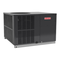
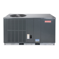
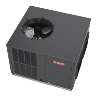
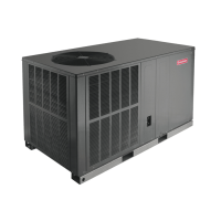
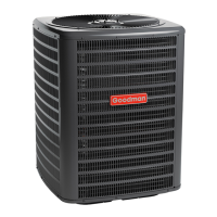
Lists the primary components of the heat pump system.
Key points to consider before starting the installation process.
Specifies required clearances for air intake, discharge, and service access.
Guidance on selecting an optimal location and preparing installation sites like ground or roof.
Safety precautions and methods for rigging and moving the unit.
Specific instructions for installing roof curbs for unit mounting.
Discusses airflow management and the need for filters.
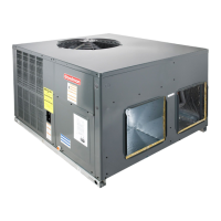
Explains how units can be converted for different airflow delivery configurations.
Details on kits required for horizontal airflow configurations.
Covers duct cover installation, down discharge applications, and general duct work guidelines.
Importance of air filters, sizing, and installation orientation.
Proper installation of the condensate drain trap for drainage.
Guidelines for electrical wiring connections, power supply checks, and compliance with codes.
Instructions for connecting high voltage power supply to the unit.
Details on connecting low voltage wires from the thermostat to the control box.
Information on internal wiring diagrams and wire replacement guidelines.
Overview of the process for starting, adjusting, and performing final checks on the unit.
Step-by-step procedure for starting the unit and a checklist of initial checks.
Specific start-up steps for the heat pump in cooling and heating modes.
Essential checks to perform after initial startup to ensure proper operation.
Description of key operational components like contactors and motors.
Explains how the heat pump operates in cooling mode, similar to an air conditioner.
Describes the heating cycle, including refrigerant flow redirection and heat exchange.
Function of the defrost control in managing frost accumulation on the outdoor coil.
Role of optional outdoor thermostats in regulating heater operation based on ambient temperature.
How the reversing valve coil is activated for cooling and defrost modes.
Function and activation of the indoor blower motor by the thermostat.
Details on selecting defrost timing periods and sensor operation.
A step-by-step guide for field testing and troubleshooting common issues.
Procedures for measuring and adjusting airflow for optimal performance.
How to adjust the indoor blower motor speed using speed taps.
Method for determining superheat using suction pressure and temperature readings.
Table correlating suction pressure with saturated suction temperature for R-410A.
Table correlating liquid pressure with saturated liquid temperature for R-410A.
Procedure for checking and adjusting subcooling and superheat for single-speed TXV systems.
Procedure for checking and adjusting subcooling and superheat for two-speed TXV systems.
Method for charging the heat pump in heating mode by weighing.
Information on installing electric heat kits and adjusting blower motor speed taps.
Recommended homeowner maintenance tasks for optimal unit operation.
Identifies common issues affecting heat pump performance in heating mode.
Explains causes and troubleshooting steps for a malfunctioning reversing valve.
A detailed chart listing common symptoms, possible causes, and remedies for unit issues.
Detailed wiring diagram for GPH15(24-36) M41A models.
Detailed wiring diagram for GPH15(42-60) M41A models.
A statement emphasizing the quality of Goodman products and factory testing.
| Type | Heat Pump |
|---|---|
| SEER Rating | 15 |
| Refrigerant | R-410A |
| Voltage | 208/230 |
| Compressor Type | Scroll |
| Phase | 1 |
| Cooling Capacity (BTU) | 24000 |
| Heating Capacity (BTU) | 24000 |
| Unit Weight (lbs) | 220 |
| Dimensions (H x W x D, in) | 34.5 x 42 x 34.5 |



 Loading...