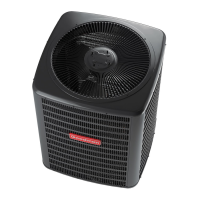
What to do if Goodman GSC13060 has too much air across indoor coil?
- JJames WardSep 23, 2025
If there is too much air across the indoor coil of your Goodman Air Conditioner, reduce the blower speed.
What to do if Goodman GSC13060 has too much air across indoor coil?
If there is too much air across the indoor coil of your Goodman Air Conditioner, reduce the blower speed.
What to do if Goodman GSC13060 has overcharge of refrigerant?
If you have an overcharge of refrigerant in your Goodman Air Conditioner, recover part of the charge.
How to fix loose connection in Goodman GSC13060?
If your Goodman Air Conditioner has a loose connection, inspect the connection and tighten it.
How to test shorted or broken wires in Goodman GSC13060?
If your Goodman Air Conditioner has shorted or broken wires, test the circuits with an ohmmeter.
What to do if Goodman Air Conditioner has noncondensibles?
If your Goodman Air Conditioner has noncondensibles, recover the charge, evacuate, and recharge.
What to do if Goodman GSC13060 Air Conditioner has not enough air across indoor coil?
If there is not enough air across the indoor coil of your Goodman Air Conditioner, increase the blower speed and check the duct static pressure.
What to do if Goodman GSC13060 has undersized liquid line?
If the liquid line is undersized in your Goodman Air Conditioner, replace the line.
What to do if Goodman GSC13060 Air Conditioner has undersized suction line?
If the suction line is undersized in your Goodman Air Conditioner, replace the line.
How to test faulty fan relay in Goodman Air Conditioner?
If your Goodman Air Conditioner has a faulty fan relay, test the continuity of the coil and contacts.
How to test shorted or grounded compressor in Goodman GSC13060 Air Conditioner?
If your Goodman Air Conditioner compressor is shorted or grounded, test the motor windings.
Unit shipped with nitrogen/helium holding charge only. Must be evacuated and charged.
Units intended for component replacement on existing systems only, not new systems.
Units must be used as replacement components for pre-2010 installed systems.
Table for determining proper system superheat based on outdoor and indoor wet bulb temperatures.
Safety precautions and steps for adjusting fixed orifice systems using a manifold gauge.
Warning regarding high voltage and necessity to disconnect all power before servicing.
Minimum technician qualifications for using this information to install or repair units.
Warning about potential injury, explosion, or death from improper refrigerant handling.
Details on obtaining and keeping the product warranty certificate.
Guidelines for inspecting units upon receipt and proper handling to prevent damage.
Requirements for installation according to national, EPA, and local codes.
Specifies minimum clearances required around the condensing unit for proper airflow.
Advice for installing units on rooftops, including structural support and vibration.
Hazards of refrigerant being heavier than air and contact with liquid refrigerant.
Warnings and procedures for handling refrigerant cylinders safely during charging.
Conditions for using returnable service cylinders for refrigerant removal.
Caution regarding compressor oil susceptibility to moisture absorption.
Guidance on routing refrigerant lines to prevent contact and ensure proper insulation.
Table of recommended refrigerant line sizes based on tonnage and length.
Specifies insulation type and minimum wall thickness for suction lines.
Checklist for burying refrigerant lines underground, including protection and sealing.
Steps for connecting refrigerant lines, including cutting, cleaning, and brazing notices.
Important notes and steps to follow when brazing refrigerant lines, including heat and materials.
Warnings about fire, explosion, and using oxygen or flammable gases for leak testing.
Safety requirements for using nitrogen for leak testing, including pressure regulators.
Method for pressure testing using nitrogen and soapy water to locate leaks.
Steps for evacuating the system to a specific micron level using a vacuum pump.
Warning about refrigerant pressure and operating the unit in a vacuum.
Caution regarding compressor damage from low suction pressure operation.
Warnings about high voltage, multiple power sources, and using copper conductors.
Notice regarding units with reciprocating compressors and non-bleed TXVs requiring a Hard Start Kit.
Guidelines for wire sizing and limiting voltage drop for proper electrical service.
Cautions regarding refrigerant leaks during valve opening and liquid refrigerant introduction.
Notice stating refrigerant must be added to the system after evacuation is complete.
Warning against overcharging the system or operating in a vacuum.
Warnings and cautions related to refrigerant pressure, compressor operation, and used refrigerant.
Notice regarding EPA regulations for refrigerant use and potential penalties.
Steps for adjusting system charge based on final conditions, checking subcooling and superheat.
Procedure for adjusting superheat in fixed orifice systems by adding or recovering charge.
Procedure for adjusting subcooling and superheat in TXV systems by adjusting the TXV.
Guide linking symptoms to possible causes and recommended test methods for diagnosis.
Notice regarding Hard Start Kits for units with rotary or reciprocating compressors.
| Cooling Capacity | 60, 000 BTU/h |
|---|---|
| SEER Rating | 13 |
| Tonnage | 5 Ton |
| Refrigerant | R-410A |
| Compressor Type | Scroll |
| Voltage | 208/230 V |
| Phase | 1 |
| Warranty | 10-Year Parts Limited Warranty |


 Loading...