3
The blower and motor bearings are permanently lubricated
and do not require additional lubrication.
EQUIPMENT
Some outdoor units have corresponding heaters that are
factory wired in such a manner that they are in operation
whenever the main power supply to the unit is on. Before
starting equipment after prolonged shutdowns or at the
time of initial start up, be sure that the circuits to the units
are closed for at least 24 hours.
APPLICATION
It is not the intent of the manufacturer that this equipment be
used with components other than indicated.
Do not connect to or use any device that is not design-
certified by Goodman for use with this unit. Serious
property damage, personal injury, reduced unit
performance and/or hazardous conditions may result
from the use of such non-approved devices.
Reference Specification Sheets For Performance Val-
ues And Approved System Matches.
LOCATION
The outdoor unit is accessible to the general public. It should
be located so that air flow through the coil is unrestricted. To
provide adequate service access, do not locate service side
closer than 30.5 cm to any wall or obstruction.
Consider the affect of outdoor fan noise on conditioned space
and any adjacent occupied space. It is recommended that the
unit be placed so that discharge does not blow toward
windows less than 7.6 m away.
The outdoor unit should be set on a solid, level foundation -
preferably a concrete slab at least 10.2 cm thick. The slab
should be above ground level and surrounded by a graveled
area for good drainage. Any slab used as a unit foundation
should not adjoin the building as it is possible that sound and
vibration may be transmitted to the structure. For rooftop
installation, steel or treated wood beams should be used as
unit support for load distribution.
Heat pumps require special location consideration in areas
of heavy snow accumulation and/or areas with prolonged
continuous subfreezing temperatures. Heat pump unit bases
are cutout under the outdoor coil to permit drainage of frost
accumulation. Units must be situated to permit free unob-
structed drainage of the defrost water and ice. A minimum
7.6 cm clearance under the outdoor coil is required in the
milder climates.
In more severe weather locations, it is recommended that
units be elevated to allow unobstructed drainage and air flow.
While there are no hard and fast rules regarding elevation, we
suggest the following minimums:
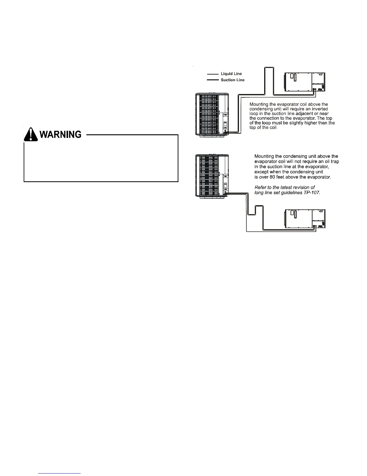
If the outdoor unit is mounted above the air handler, the
maximum lift should not exceed 21.3 m (suction line). If air
handler is mounted above condensing unit, the lift should not
exceed 15.2 m (liquid line).
INSTALLATION, ELECTRICAL
The supply power, voltage, frequency and phase must coincide
with that on unit nameplate. All wiring should be carefully
checked against the manufacturer’s diagrams. Field wiring
must be connected in accordance with the National Electric
Code or other local codes that may apply. Make certain that
the equipment is adequately grounded per local code re-
quirements.
The manufacturer bears no responsibility for damage caused
to equipment or property as a result of the use of larger than
recommended size protective devices as listed on the unit
rating plate.
This equipment has been started at minimum rated voltage
and checked for satisfactory operation. Do not attempt to
operate this unit if available voltage is not within the minimum
and maximum shown on nameplate.
Insulation of at least 1.3 cm wall thickness should be used on
the suction line to prevent condensation when cooling and
heat loss when heating. The insulation should be installed on
the tubing prior to installation and should be run the entire
length of the installed line. The end of the tubing over which
the insulation is being slipped should be covered to insure
that no foreign material is introduced to the interior of the
tubing. The outdoor units are equipped with two service
valves, and, “as shipped”, the valves are in the front-seated
or “closed” position.

 Loading...