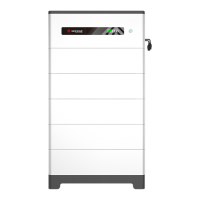
What to do if Goodwe Battery Pack shows BMU Communication Fault?
- SSusan SotoSep 12, 2025
If your Goodwe Battery Pack is showing a BMU Communication Fault, restart the battery. If the problem persists, contact after-sale service.

What to do if Goodwe Battery Pack shows BMU Communication Fault?
If your Goodwe Battery Pack is showing a BMU Communication Fault, restart the battery. If the problem persists, contact after-sale service.
What to do if Goodwe Battery Pack has MCU Internal Communication Fault?
If your Goodwe Battery Pack has an MCU Internal Communication Fault, restart the battery. If the problem persists, contact after-sale service.
| Brand | Goodwe |
|---|---|
| Model | Lynx Home F Series |
| Category | Camera Accessories |
| Language | English |
Lists the compatible models for this user manual.
Identifies the intended readers of the manual.
Explains the meaning of warning symbols used in the manual.
Details the version history and changes made to the manual.
Provides general safety guidelines for operating the equipment.
Outlines specific safety measures related to the battery system.
Details procedures for handling emergencies like leaks or fires.
Lists directives the product complies with for the European market.
Introduces the battery system and its intended use.
Illustrates how the battery system is used in a solar energy storage setup.
Shows the physical components and parts of the battery system.
Provides the physical dimensions of the battery system.
Lists checks to perform before accepting the product.
Details the components included with the battery system.
Specifies the correct procedures and environment for storing the equipment.
Outlines the necessary conditions for installing the battery system.
Provides step-by-step instructions for installing the battery system.
Highlights safety rules specific to electrical connections.
Details the process of connecting electrical components.
Explains how to connect the protective earth (PE) cable.
Guides through connecting the power cables.
Describes how to connect communication cables.
Details the connection of the terminal resistor.
Instructs on how to install the protective cover.
Lists checks before powering on the system.
Provides steps for powering on the battery system.
Explains how to configure the battery system parameters.
Describes the meaning of different indicator lights on the system.
Shows the external appearance of the main battery system unit.
Details the appearance of an individual battery module.
Illustrates the design of the base unit for the battery system.
Shows the appearance of the right side of the power control unit.
Shows the appearance of the left side of the power control unit.
Shows the appearance of the front of the power control unit.
Shows the appearance of the bottom of the power control unit.
Details the environmental conditions required for installation.
Instructions on how to safely move the battery system before installation.
Step-by-step guide for installing the battery system itself.
Details installation for systems without adjustable feet.
Details installation for systems with adjustable feet.
Details the process for connecting power cable Type 1.
Explains connection for 4-6mm² power cables.
Details the process for connecting power cable Type 2.
Instructions for powering on a single battery system.
Steps for installing and connecting the PV Master app.
Guide for setting the battery model using the PV Master app.
Details the indicator lights during normal operation.
Steps to safely power off the battery system for maintenance.
Outlines a schedule for regular maintenance checks.