© Gooligum Electronics 2015 www.gooligum.com.au
Baseline and mid-range PIC training and dev board operation guide Page 4
Operation
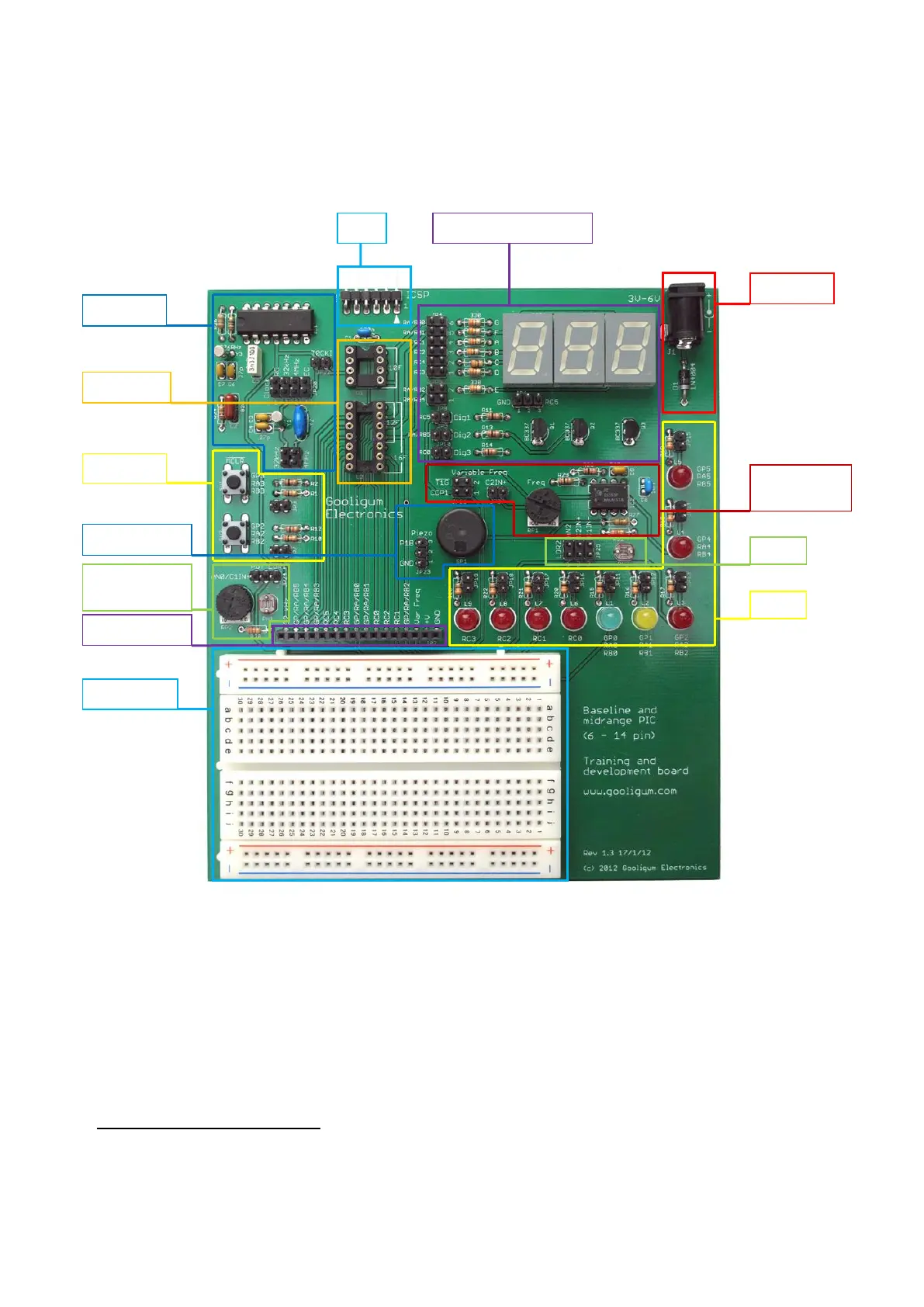
The training board consists of a number of functional blocks, as shown:
Plug your PIC microcontroller into one of the PIC sockets:
Socket U1, marked ‘10F’, is for PIC10F devices
The upper section of socket U2, marked ‘12F’, is for 8-pin PIC12F devices
The whole of socket U2, marked ‘16F’, is for 14-pin PIC16F devices
Note: you must plug a PIC into ONLY ONE socket at once. If you’ve been using a PIC10F and want to
use a PIC12F or PIC16F, remove the PIC10F from the ‘10F’ socket first!
Although PIC10Fs are 6-pin devices, only those supplied in 8-pin DIP packages can be used (directly) with this
training board. Only 6 pins of the 8-pin package are available for use; the PIC10F is still a 6-pin device.
Variable freq.
oscillator
 Loading...