EasyManua.ls Logo

GORBEL G-Force Q Series - User Manual

Default Icon
60 pages
Print Icon
To Next Page IconTo Next Page
Loading...
IMPORTANT!
DO NOT DESTROY
Installation &
Operation Manual
Month
Year
Gorbel
®
Dealer
Date
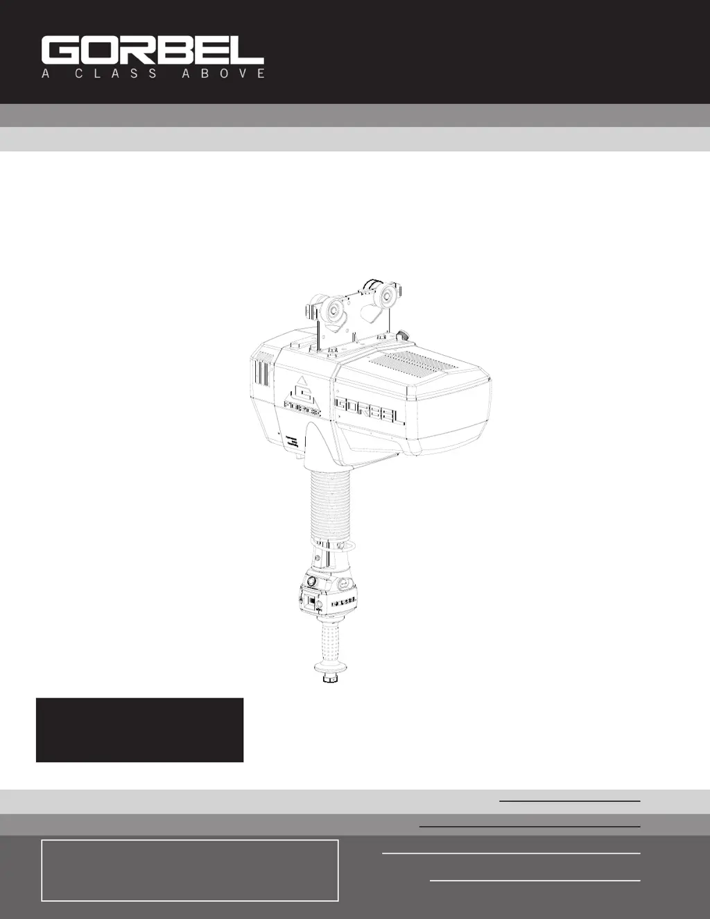
G-Force®
Q and iQ Series
Gorbel
®
Customer Order No. / Serial No.
®
Go to www.gorbel.com/support/warrantyregistration.aspx
to register your G-Force®, sign up for our Platinum
Service Package and request your free G-Force® Q and
iQ Series Service Manual.

Questions and Answers

  • R
    Raymond DuncanAug 19, 2025
    What to do if GORBEL Servo Drives unit will not raise or lower the load?
    • D
      David CarrollAug 19, 2025
      If your GORBEL Servo Drives unit isn't raising or lowering the load, make sure you are in the RUN MODE. Also, check the virtual limits settings if your unit is equipped with that option and ensure that you are not in an overloaded condition. If you are wearing dark gloves, remove them and try using the sliding handle again. Check the coil cord connections at both the handle and the actuator. Ensure that the sliding handle grip or pendant handle levers move smoothly and check for any interference between the handle and any foreign objects or work surfaces.
  • W
    Whitney RussoAug 21, 2025
    What to do if GORBEL G-Force Q Servo Drives Float Mode does not function correctly?
    • J
      Joseph AllenAug 21, 2025
      If the Float Mode on your GORBEL Servo Drives isn't working correctly, first check that your system has the Float Mode option and that the blue LED on the handle is illuminated. Also, check to see if the LCD screen indicates you are in Float Mode and that Float Mode has not timed out because the system has not been used for 60 seconds. Ensure the unit is stable when Float Mode is initiated, and that the load data is reading accurately on the LCD screen. Verify the bridge capacity, checking for excessive deflection in the bridge, and check for obvious interference with the coil cord or handle.
  • K
    karen14Aug 23, 2025
    Why GORBEL Servo Drives unit only goes in the up direction?
    • J
      james80Aug 25, 2025
      If your GORBEL Servo Drives unit is only moving upwards, check the virtual limits settings if equipped with that option. Ensure that the wire rope is not slack and check for any obvious interference with the load or the handle. Also, verify that you are not at the lower limit of the system. Check the coil cord connections at both the handle and actuator, and inspect the overall condition of the coil cord, looking for broken or exposed wiring.
  • L
    Lisa McclureAug 26, 2025
    Why GORBEL G-Force Q Servo Drives unit only goes in the down direction?
    • T
      Theresa FlemingAug 26, 2025
      If your GORBEL Servo Drives unit is only moving downwards, check the virtual limits settings if equipped with that option. Ensure that you are not at the upper limit of the system and that you are not in an overload condition. Check for any obvious interference with the load or the handle. Check the coil cord connections at both the handle and actuator, and the overall condition of the coil cord, looking for broken or exposed wiring.
  • A
    Angela PopeAug 28, 2025
    What does it mean when GORBEL Servo Drives shows 7219 / 4005 codes?
    • D
      Dillon ChapmanAug 28, 2025
      The 7219 / 4005 codes on your GORBEL Servo Drives indicate that the AC power is too low. If it approaches approximately 200VAC, the system will not operate properly.
  • D
    David KleinAug 30, 2025
    How to fix GORBEL G-Force Q Servo Drives if it is too slow or too fast?
    • C
      Casey CarrollAug 30, 2025
      To adjust the speed of your GORBEL Servo Drives, go to PROGRAM MODE. Also, check for speed reduction setting in virtual limits program if equipped with that option.
  • M
    Matthew DaySep 2, 2025
    How to fix GORBEL G-Force Q Servo Drives unit if it will not raise or lower the load to the desired height?
    • S
      Shawn MeyersSep 2, 2025
      To resolve issues with your GORBEL Servo Drives not reaching the desired height, check the virtual limits settings in PROGRAM MODE. Also, inspect for wire rope damage. Verify whether you have an extended wire rope with a standard length coil cord, and check to see if the wire rope has been modified (shortened) for any reason. Finally, check for any interference with foreign objects, tooling, or work surfaces.
  • P
    Paul JacksonSep 4, 2025
    How to fix GORBEL G-Force Q unit if it does not accelerate at the desired rate?
    • M
      Michael StewartSep 4, 2025
      To adjust the acceleration rate of your GORBEL Servo Drives, adjust the response in PROGRAM MODE. Ensure that you are not attempting to “snatch” the load. Check the weight of the load; if you are close to the overload limit, try lifting at a reduced speed.
  • M
    marissazamoraSep 6, 2025
    What does it mean when GORBEL Servo Drives shows 501 / 11000 codes?
    • C
      Chloe SandersSep 6, 2025
      The 501 / 11000 codes on your GORBEL Servo Drives indicate a limit switch fault. To resolve this: 1. Ensure there is weight on the hook. 2. Disconnect AC power. 3. Reapply AC power.
  • W
    wrightterriSep 8, 2025
    Why is the GORBEL G-Force Q actuator extremely noisy?
    • F
      fchandlerSep 9, 2025
      If the actuator of your GORBEL Servo Drives is making excessive noise, check the condition of the wire rope and inspect for any external damage to the actuator covers.

Summary

SAFE HOIST OPERATING GUIDELINES

G-FORCE MAIN ASSEMBLY COMPONENTS

INSTALLATION PROCEDURES

Step 1 - Unpacking the G-FORCE

Details the process of unpacking the G-Force® unit and verifying components.

Step 2 - Pre-Assembly and Tools

Lists the tools and materials required before beginning the G-Force® installation.

Step 3 - Actuator Assembly Installation

Provides instructions for installing the G-Force® actuator onto the trolley or bridge system.

Step 4 - Coil Cord Installation

Guides the user through connecting and securing the coil cord assembly to the actuator.

Step 5 A - In-Line Slide Handle Installation

Instructions for installing the in-line slide and in-line force sensing handles.

Step 5 B - Remote Mounted Slide Handle Installation

Details the process for installing the remote mounted slide handle.

Step 5 C - Suspended Pendant Handle Installation

Provides instructions for installing the suspended pendant handle assembly.

Step 5 D - Remote Mounted Pendant Handle Installation

Guides the user through installing the remote mounted pendant handle.

LIFT FUNCTIONALITY

CONTROLS INTERFACE FEATURES

PROGRAM MODE OPERATION

TROUBLESHOOTING

Basic Troubleshooting Guide

Offers solutions for common operational issues and error messages.

System Fault Diagnostics Chart

Lists error codes and their corresponding corrective actions for system faults.

TECHNICAL SPECIFICATIONS

WIRE ROPE INSPECTION AND MAINTENANCE

SLACK SPRING ADJUSTMENT

INSPECTION AND MAINTENANCE SCHEDULE

GORBEL G-Force Q Series Specifications

General IconGeneral
BrandGORBEL
ModelG-Force Q Series
CategoryServo Drives
LanguageEnglish

Related product manuals