STEP 5 - BRIDGE AND END TRUCK INSTALLATION (CONTINUED)
Extended End Trucks (continued)
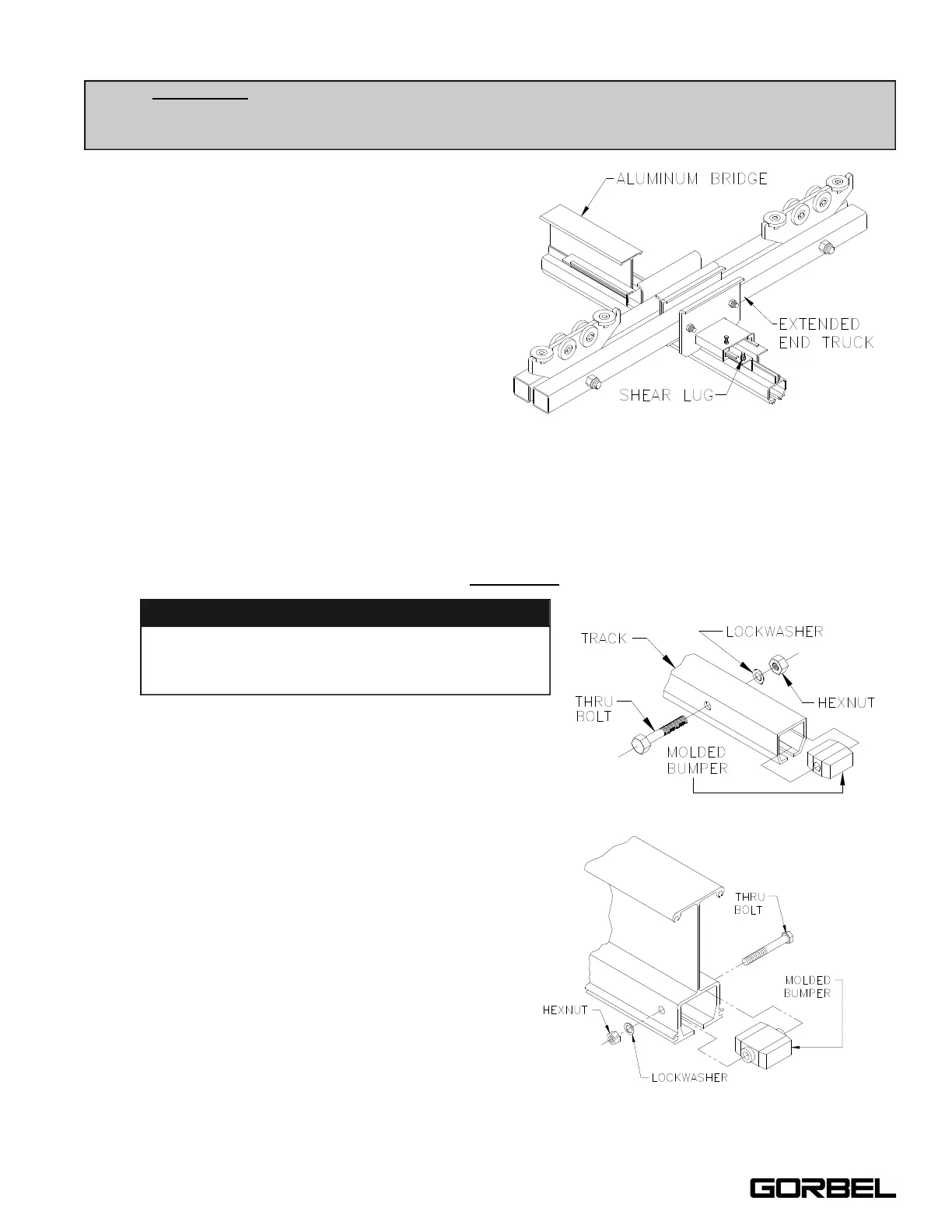
5.34 Slide an end truck over festooning end
of bridge (refer to the General
Arrangement Drawing for exact end
truck location) and clamp into place
(diagram 5M).
Note: The festooning end of the bridge
will have a hole that is inset the same or
greater distance from the end of the
bridge than the hole in the opposite end
of the bridge.
5.35 Slide and position the non-clamping end
truck on the other end of bridge (refer to
the General Arrangement Drawing for exact location).
5.36
At both ends of bridge, install a shear lug bolt in the hole in the coped brackets to prevent
bridge from sliding out of end trucks (diagram 5M).
Note: Install bolts with head of bolt on underside of top flange with threads pointing up.
5.37 Install an end stop to the end of the bridge
opposite the festooning (diagrams 5N or 5O).
5.38 Lift bridge up to runways and
simultaneously insert end trucks into
open ends of runways. Make sure
festooning end of bridge is oriented
with festooning runway. For
information on festooning, refer to
Step 8, on page 18.
5.39 Immediately install end stops in
open ends of runways to prevent
bridge from exiting runways
(diagrams 5N or 5O).
5.40 Roll bridge down length of runways
to check for smooth travel. If travel
is not smooth, check track for level
and parallel (Step 3.3, page 6) and
check to make sure that only one
end truck on bridge is clamped.
TIP: ONLY ONE
end truck is clamped to the bridge: the other is not. The clamping end truck
must be oriented with the festooning side of the track (refer to Step 8, on page 18 for
festooning). The non-clamping end truck allows adjustment for any runway misalignment.
Diagram 5N. Installing end stop.
Diagram 5O. Installing end stop.
13
9/05
Diagram 5M. Installing extended clamping end truck.
See TIP.
WARNING
Failure to install shear lug bolt assemblies may
result in the bridge, hoist, and load falling to the
floor.