STEP 2 - HANGER INSTALLATION
Top Hanger Assemblies
2.1 Mark top hanger placement on the building support
beams and runway/monorail track (refer to the General
Arrangement Drawing, inserted in this manual, for
hanger placement). Installation parameters can be
found on page 22.
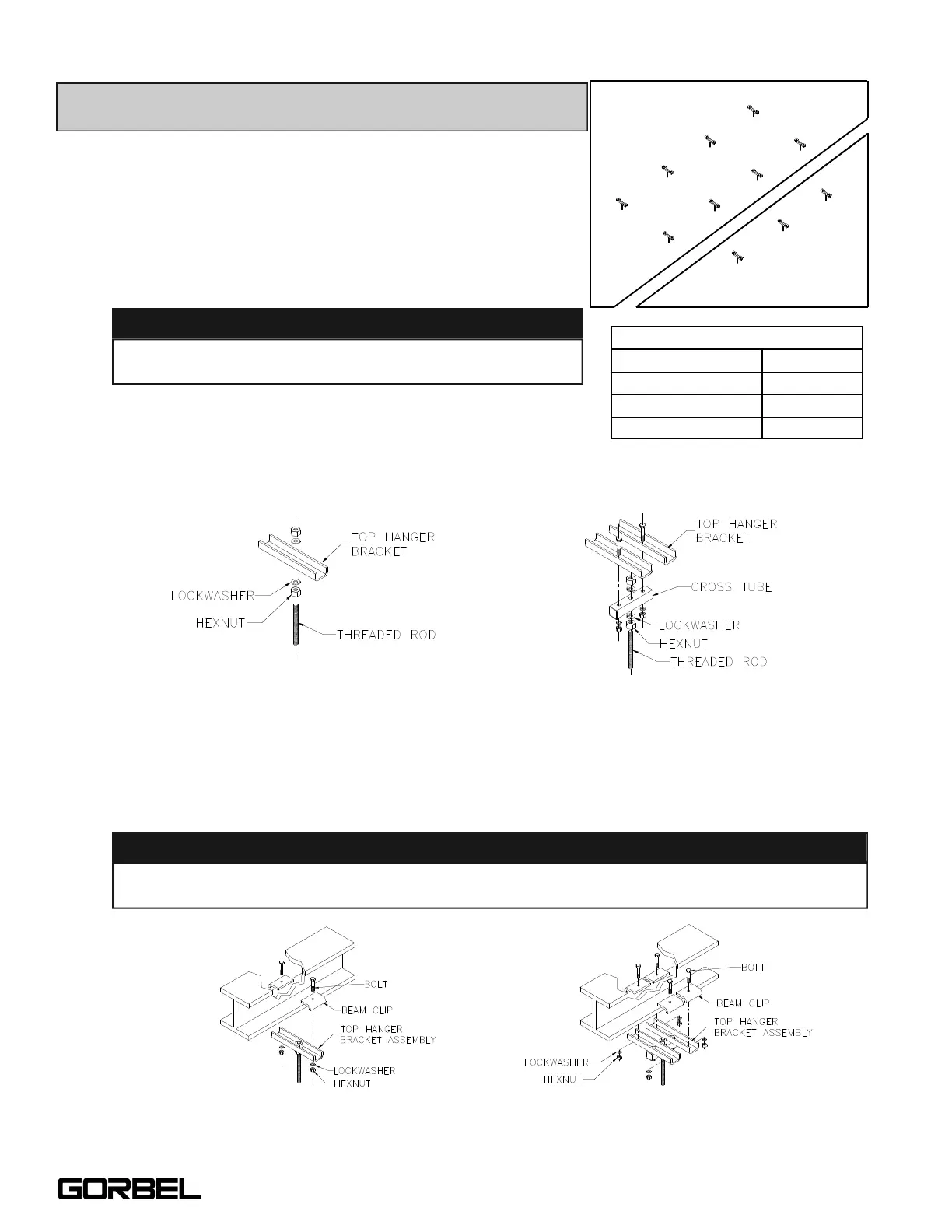
2.2 To attach threaded rod to top hanger bracket:
Assemble top hanger assembly (diagram 2A). Refer to
Chart 2A for proper nut torque.
2.3 Bolt top hanger bracket assembly and beam clips to building support beam
(diagram 2B). Note: Flange thickness may vary and require shimming. Shimming
may be needed to assure that the beam clip hardware is vertical.
TIP: Standard top hanger brackets are designed for flange
widths from 1”-3”, 3-1/4”-5-1/4”, 5-1/2”-7-1/2”, 8”-10”.
WARNING
Threaded rod must have a minimum of two threads
beyond the hexnut.
Chart 2A. Torque Chart.
4000#250-2000#
Diagram 2A. Attaching threaded rod to top hanger bracket.
WARNING
250-2000# 4000#
Diagram 2B. Bolting top hanger bracket and beam clips to existing support beam.
2
9/05
“Center hole” of the top hanger bracket assembly must be centered on building support
beam.
Bridge Crane
Monorail
Bolt Diameter
1/2”
5/8”
3/4”
Torque
50 ft.-lb.
95 ft.-lb.
150 ft.lb.
TORQUE CHART