STEP 2 - HANGER INSTALLATION (CONTINUED)
Lower Hanger Assemblies
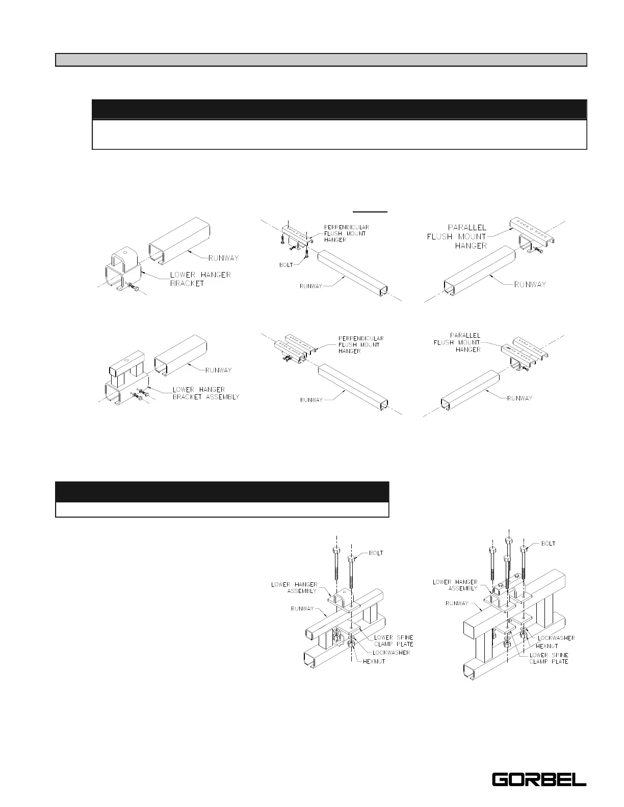
2.4 For untrussed (plain) track:
Slide lower hanger assembly over the runway track and bolt into place with clamping bolts
(diagram 2C).
Note: Install the vertical bolts for beam clips (Step 3.2, on page 5) on the Perpendicular
Flush Mount Hanger 250-2000# (diagram 2C), before sliding it on the track.
For trussed track:
Bolt the lower hanger assembly and
lower spine clamp plate to the top
truss tube of runway (diagram 2D).
Torque nuts (chart 2A, page 2, for
proper torque rating).
Note: Sway brace brackets should
be installed at this time (see page
23).
WARNING
Do not over-tighten clamping bolts on the lower hanger assemblies: this will cause
permanent damage to the runway track.
Plain Track 250-2000# Perpendicular Flush Mount 250-2000# Parallel Flush Mount 250-2000#
Plain Track 4000# Perpendicular Flush Mount 4000# Parallel Flush Mount 4000#
Diagram 2C. Installing lower hanger assemblies on untrussed (plain) track.
WARNING
Bolts must have a minimum of two threads beyond hexnut.
Trussed Track 250-2000# Trussed Track 4000#
Diagram 2D. Bolting lower hanger assembly and spine
clamp plate to trussed track.
3
9/05