3
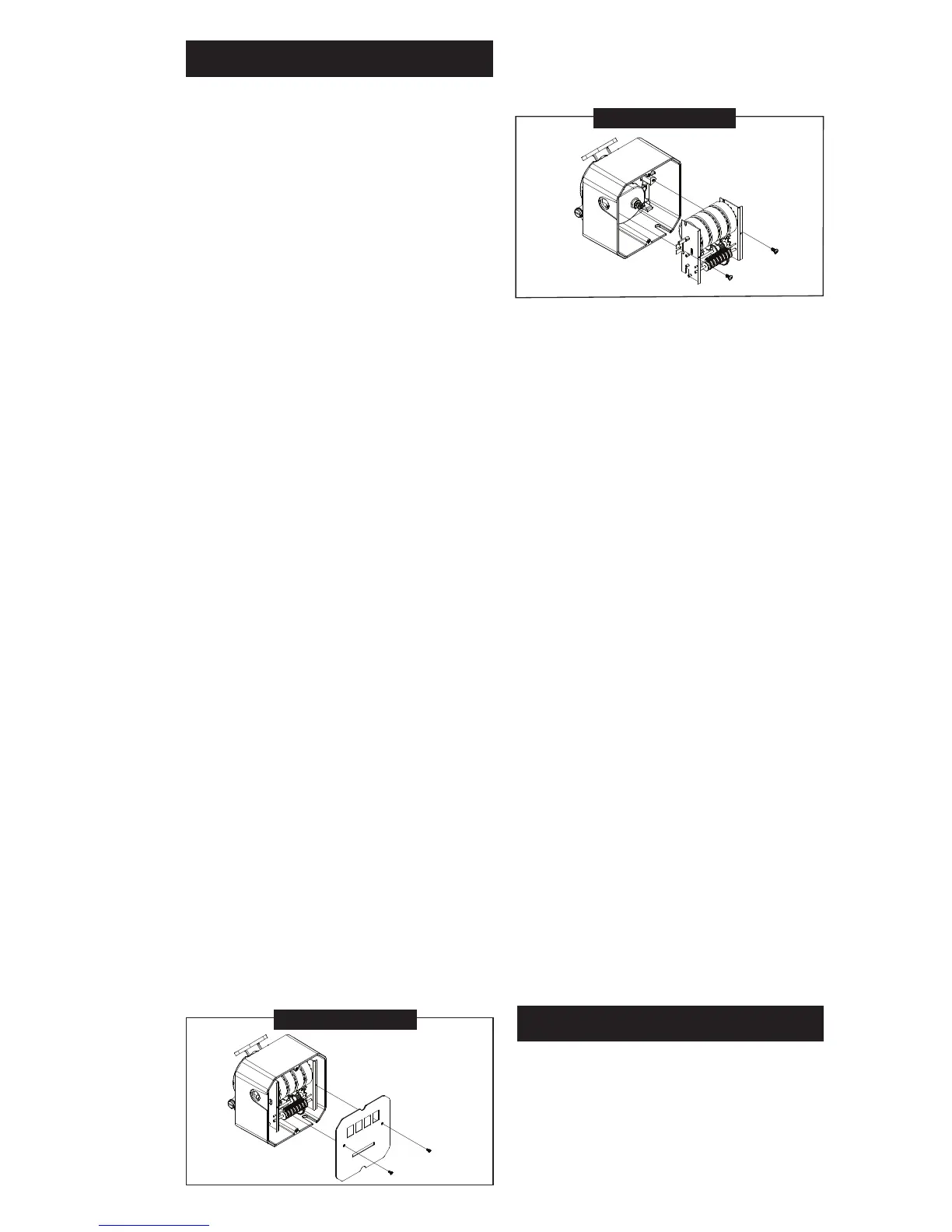
FIGURE 1
INSTALLATION
Before installing your meter, review
the safety instructions given above.
Examine your meter to make sure
there are no visible signs of shipment
damage. Plan your meter installation
by reviewing the following procedures.
Your system must be mounted on a
vented tank. If the tank is unvented,
your local dealer or distributor can
supply a pressure cap.
If the meter is located in a rigid piping
system where the uid is trapped
(for example, by gravity, valves or
nozzles) thermal expansion of the
uid can create pressure spikes that
can damage a meter.
Install a thermal relief valve or oth-
erwise allow for thermal expansion
of the uid.
Prior to installation, determine the
tting angle desired and whether
horizontal or vertical orientation is
required.
Rotate Fittings
To rotate inlet and/or outlet ttings,
remove the two nuts and bolts that
secure each tting. Rotate the tting
to the desired orientation. Make sure
the O-ring is fully seated. Tighten the
nuts and bolts snugly.
C
hange Orientation
1. Pull the knob to remove from unit.
Remove screws that hold bezel
in place and set aside.
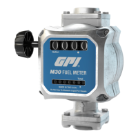
2. Remove the two screws that hold
the faceplate in place and remove
faceplate. (Figure 1)
FIGURE 2
3. Remove two screws to release
the counter assembly. (Figure 2)
4. Remove the bevel gear from the
center of the coverplate. Remove
the eight pairs of nuts and bolts
that hold the coverplate assembly
in place.
5. Now you can rotate the coverplate
to the desired orientation. Reas-
semble in reverse order, making
sure the O-ring is fully seated.
Torque eight nuts and bolts to
60 - 72 in-lb.
Meter Installation
1. Remove protective plugs from
the meter inlet and outlet ports.
2. Wrap threaded male connections
with thread tape or use a pipe
sealant compound compatible
with petroleum fuels. We recom-
mend thread sealant at the inlet
tting in horizontal orientation.
3. Install the meter on the pump us-
ing an appropriately sized nipple.
The meter’s ow path is marked on
the housing exterior with an arrow
pointing toward the outlet port.
4. Install other system components
on the meter and tighten snugly.
OPERATION
ALWAYS FOLLOW SAFETY PRE-
CAUTIONS WHEN OPERATING
THIS EQUIPMENT. REVIEW THE
SAFETY INSTRUCTIONS. Before
each use, visually check the meter
to ensure it is securely connected to
 Loading...