TABLE OF CONTENTS
English ........................................................... 1
Español ..........................................................9
Deutsch .......................................................16
Italiano .........................................................23
Français ....................................................... 30
ENGLISH
IMPORTANT NOTICE
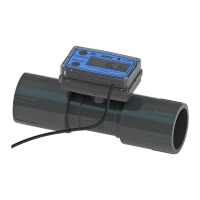
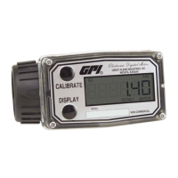
Use TM Series meters with water and other
chemicals compatible with wetted components
(see Specifications Section). Do not use to meter
fuel or incompatible chemicals. TM Series meters
are available with either a computer for local
electronic display, or a conditioned signal output
module to provide a digital signal to customer
interfacing equipment. TM Series meters with
computer display measure in gallons or litres.
Refer to the Calibration Section for details.
These meters are not legal for trade applications.
TM Series meters are very sensitive to electric
noise if operated within 1 to 2 inches of some
electric motors or other sources of electronic
noise.
TM Series Electronic Water Meters
User Manual
Rev. A 920861-01
04/13
INSTALLATION
Connections
Install your meter in-line either horizontally or
vertically or at the end of the hose adjacent to
the nozzle. Installation to metal connections is
not recommended. Install as follows:
1. Plan to install turbine with a minimum straight
pipe length as follows:
• Upstreamfromtheturbine,allowamini-
mum straight pipe length of 10 times the
internal diameter of the turbine.
• Downstream from the turbine, allow a
minimum straight pipe length of 5 times
the internal diameter of the turbine.
2. For Spigot (Pipe) End use only primer and
solvents approved for PVC gluing.
Cut to Length The meter housing can be
shortened by the customer. Each meter has
a “dotted” line feature molded on the top
surface of the housing tube. The housing
can be cut up to this line without harming
any internals.
Most glue on fittings will fit without interfering
with the computer display area. However,
the customer should check all parts before
attempting cut.
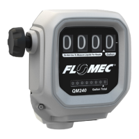
TM Meter with Computer Display TM Digital Pulse Meter
Save theSe inStructionS
www.calcert.com sales@calcert.com1.800.544.2843
0
5
10
15
20
25
30