OM−02806
0 SERIES
MAINTENANCE & REPAIR PAGE E − 5
Separating Pump From Engine
If the impeller, seal of other pump parts are to be
serviced, the rotating portion of the pump must be
separated from the engine.
Remove the hardware (19 and 20) securing the in-
termediate (39) to the engine bellhousing.
Using a hoist and sling of suitable capacity, sepa-
rate the pump from the engine by pulling straight
away from the engine.
As the assemblies separate, the flexible element
(28) of the coupling will remain on the shaft. To re-
move the flexible element, remove the hardware
(32 and 33) securing the clamping ring (29) and
hub (31) to the bushing (37).
Install two 1/4−20 UNC x 2−1/2 inch long caps-
crews (not supplied) in the pusher holes in the cir-
cumference of the clamping ring (29). Turn the
screws evenly in an alternating sequence until the
coupling separates from the bushing, and slide the
coupling off the shaft. Further disassembly of the
coupling is not necessary.
To remove the bushing (37), loosen the setscrews
securing it to the shaft. Remove the shaft key (36).
It is not necessary to remove the connection ring
(27) from the engine flywheel unless replacement
is required. To remove the ring, disengage the
hardware (21 and 22) securing it to the flywheel.
Move the pump to a clean, well-equipped shop for
further maintenance and repair.
Impeller Removal
To remove the impeller, block impeller rotation by
inserting a 1/2-inch steel rod between the vanes of
the impeller (2). Use caution not to damage the im-
peller.
Install the shaft key (36). Install a lathe dog on the
drive end of the shaft (49) with the V" notch posi-
tioned over the shaft key.
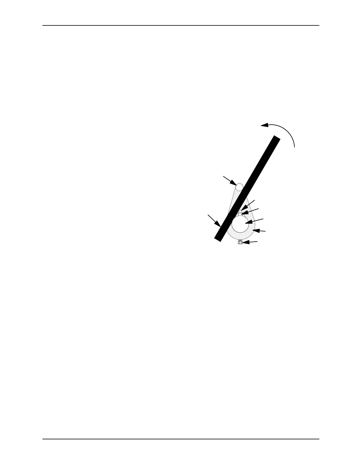
With the impeller rotation blocked, see Figure 2
and use a long piece of heavy bar stock to pry
against the arm of the lathe dog in a counterclock-
wise direction (when facing the drive end of the
shaft). Use caution not to damage the shaft or key-
way. When the impeller breaks loose, remove the
lathe dog, key and wood block.
Turn
Counterclockwise
Lathe Dog Arm
V" Notch
Shaft Key
Impeller Shaft
Lathe Dog
Setscrew
Heavy
Bar Stock
Figure 2. Loosening Impeller
After the impeller breaks loose, remove the lathe
dog, shaft key and steel rod. Unscrew the impeller
using caution; tension on the seal spring will be re-
leased as the impeller is unscrewed.
Remove the impeller adjusting shims (23). For
ease of reassembly, tie and tag the shims, or mea-
sure and record their thickness.
If no further disassembly is required, proceed with
Impeller Installation.
Seal Removal And Disassembly
Carefully remove the spring centering washer (25)
and seal spring. Slide the shaft sleeve (24) and ro-
tating portion of the seal off the shaft as a unit. Ap-
ply oil to the sleeve and work it up under the bel-
lows. Slide the rotating portion of the seal off the
sleeve.
Use a pair of stiff wires with hooked ends to remove
the stationary seat.


 To Next Page