OM-06704 PA SERIES
PAGE B - 8 INSTALLATION
Float Switch Installation
The Float Switch autostart system employs either a
single or double float switch, where a bulb raises or
lowers (floats) with the liquid level, thus activating
an enclosed miniature switch. The floats are
equipped with a socket type connector that plugs
into a matching receptacle on the auto‐start control
box.
Standard floats are equipped with 50 feet (15,2 m)
of cable.
When installing the floats, note the following:
a. Be sure to provide sufficient room in the wet
well or sump so that floats do not get ob
structed or drawn into the suction line. If a flex
ible suction hose is used, it may be extended
to lay along the bottom of the wet well or sump
and the float can be attached to the hose
above the point where it bends along the bot
tom. Direct the suction line toward the flow,
and the float(s) away from the flow. If a stand
pipe is available, attach the float switch cable
to the standpipe in the sump at the approxi
mate desired liquid level.
b. In a single float system, the cable can be teth
ered to the suction line or standpipe approxi
mately 6 inches (152 mm) above the float.
This setting allows approximately 9 inches
(229 mm) of liquid rise between pump start/
stop. The start/stop interval may be increased
by extending the float end of the cable. The
liquid level in the sump will increase approxi
mately 8 inches (203 mm) between start/stop
intervals for every 6 inches (152 mm) of cable
increase.
c. If a double float switch system is used, posi
tion the “Start” float at the desired high water
level in the sump, and the “Stop” float at the
desired low water level in the pump.
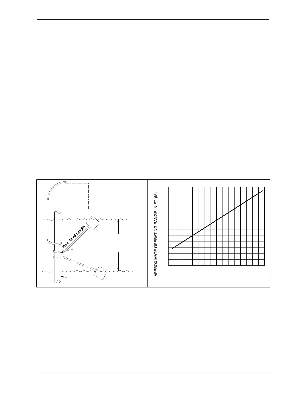
d. Refer to Figure 4 for additional float switch
data.
OPERATING
RANGE
(See Table Below)
CABLE
TETHER
POINT
OFF
(Emptying)
ON
(Filling)
ON
(Emptying)
OFF
(Filling)
1.25” Pipe
(Not Furnished)
PUMP
CONTROL
BOX
1.0
(0.3)
APPROXIMATE FREE CORD LENGTH IN FT. (M)
0.5
(.15)
1.0
(0.3)
1.5
(.46)
2.0
(0.6)
2.5
(.76)
3.0
(0.9)
2.0
(0.6)
3.0
(0.9)
4.0
(1.2)
Figure 4. Float Switch Data
Submersible Transducer Installation
The Electronic Pressure Switch (EPS) autostart
system employs a submersible transducer level
sensor with 75 feet (22,9 m) of signal cable con
nected to the EPS.
The transducer sensor converts pressure to an
electrical signal proportional to liquid level. This
electrical signal is distributed to the digital display
on the EPS through a scaling circuit which con
verts the electrical signal to “feet of water”.
When installing the transducer sensor, note the fol
lowing:
a. Handle the signal cable and transducer sen
sor with care during installation. Carefully
lower the sensor into the wet well or sump; do
not drop it to the bottom. To avoid clogging,
suspend the sensor off the bottom.
 Loading...