OM-06704 PA SERIES
PAGE B - 10 INSTALLATION
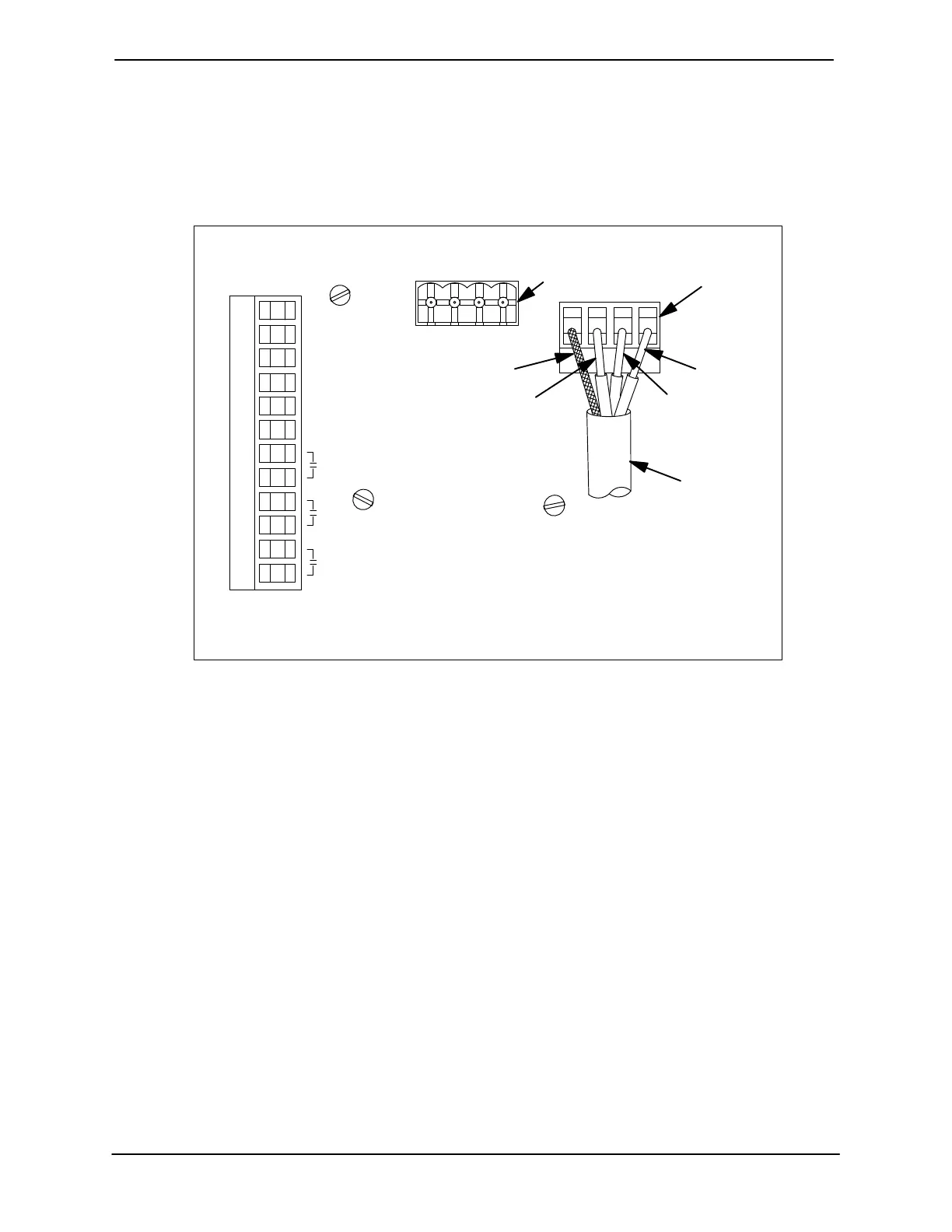
Transducer Connections
The submersible transducer sensor cable is facto
ry‐equipped with a female connector which mates
with a male connector on the back of the EPS con
trol. If removal or replacement of the female con
nector is required, reconnect the cable to the con
nector as shown in Figure 6.
Once the connections are made, simply plug the
female connector into the male connector on the
back of the EPS, and refer to Section C for opera
tional procedures.
SHD -V +VSIG
+ BATT
- BATT
SHIELD
-
MOTOR
RUN
+
+ TEMP
RELAY
A
RELAY
B
HORN
RELAY
TRANSDUCER
CAUTION-
THIS COVER PLATE MUST
BE INSTALLED FOR PROPER
CONTROL OPERATION
MALE
TRANSDUCER
CONNECTOR
FEMALE
TRANSDUCER
CONNECTOR
TRANSDUCER
SENSOR
CABLE
RED
WHITE
BLACK
SHIELD
Figure 6. Back Side of Transducer Showing Sensor Cable Connections
 Loading...