20 308899
Service
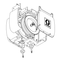
Fig. 17
18a
36
C
31
A
6
03727A
9. To remove the roller support assembly (A),
remove the three screws (18a), and lift the arm off
the reel. See Fig. 17.
10. Remove the nut (6), and remove the hose drum
(C) from the base (36). Lay the drum on a work
bench with the ratchet (31) side down.
11. For Low- and Medium-Pressure Hose Reels,
remove the retaining ring (12), swivel (34),
retaining ring (11), and spacer (21). See Fig. 15
on page 18.
For High-Pressure Hose Reels, remove the swivel
assembly (34), retaining ring (11), and spacer (21).
See Fig. 14 on page 18.
12. Before you continue with this procedure, read
the Warning below.
WARNING
Use extreme caution when handling the spring.
The spring (25), which is located behind the flange
(26), is always under great tension and could be
propelled from the lower flange with enough force
to cause serious injury. See Fig. 18.
To reduce the risk of serious injury when doing any
repair work that exposes you to the spring, be sure
to carefully follow the instructions below. Be sure
you understand this procedure before continuing
with the repair work.
13. Remove the screws (13), nuts (9), and retaining
ring (28) from the reel flanges (26 and 40). See
Fig. 18 on page 21 and the Parts Drawing on
page 22.
14. Lay the reel flat. With extreme caution, lift up on
the flange (26) to expose the spring (25).
15. Carefully inspect the spring.
If either end of the spring (25) is worn or damaged
and does not hook properly on the reel hub (24) or
the pin (C), the spring needs to be replaced. See
Fig. 18. If the pin itself is broken, the lower reel
flange (40) must be replaced.
16. To remove the spring, use locking pliers (A) placed
near the end of the spring, as shown, to compress
several rows of the spring (25) together, and lift out
the spring. See Fig. 18.
17. Before disposing of the spring, carefully attach a
minimum of two hose clamps (B) around the
keeper (D) and spring (25) bands as shown in
Fig. 19.
18. When greasing and installing the new spring, coat
the new spring and the flange (40) with a multi-
purpose, lithium-based grease before installing the
spring. Use a locking pliers (A) to compress
several rows of the spring (25) together. See
Fig. 18.
 Loading...