Valve Assembly Installation
313230F 5
c. Remove the indicator pin by sliding it through
the slot on models equipped with this arrange-
ment (MS and late model MX type) or drive out
cross pin using a brass rod (old MX type).
d. Discard the pin.
e. Carefully insert piston back into the bore.
f. Plug the hole with piston plug removed in step
4. Torque to 12 ft-lb (16.3 N•m) for MSP, 35
ft-lb (47.5 N•m) for MX.
7. Make electrical connection.
Method B: Replacing existing cycle
indicator pin/switch
1. Determine which valve section and side is the most
convenient location for the switch.
2. Relieve pressure. See Pressure Relief Procedure in
the pump instruction manual included with your
operating system.
3. Remove the existing cycle indicator pin/switch.
4. Reverse piston so the proximity switch does not
sense slot end of piston.
5. Install the appropriate proximity switch into the pis-
ton chamber using the supplied seal/gasket. For
MS and MH valve sections, torque to 6-8 ft-lb (8 -
10.8 N•m) for o-ring seal; 10 ft-lb (13.6 N•m) for
gasket seals. For MX and MGO torque adapter to
25-30 ft-lb (33.9 - 40.7 N•m) and the switch to 6-8
ft-lb (8 - 10.8 N•m).
Wiring Instructions
In order to make proper electrical connections, a “CH”
style connector cable must be used.
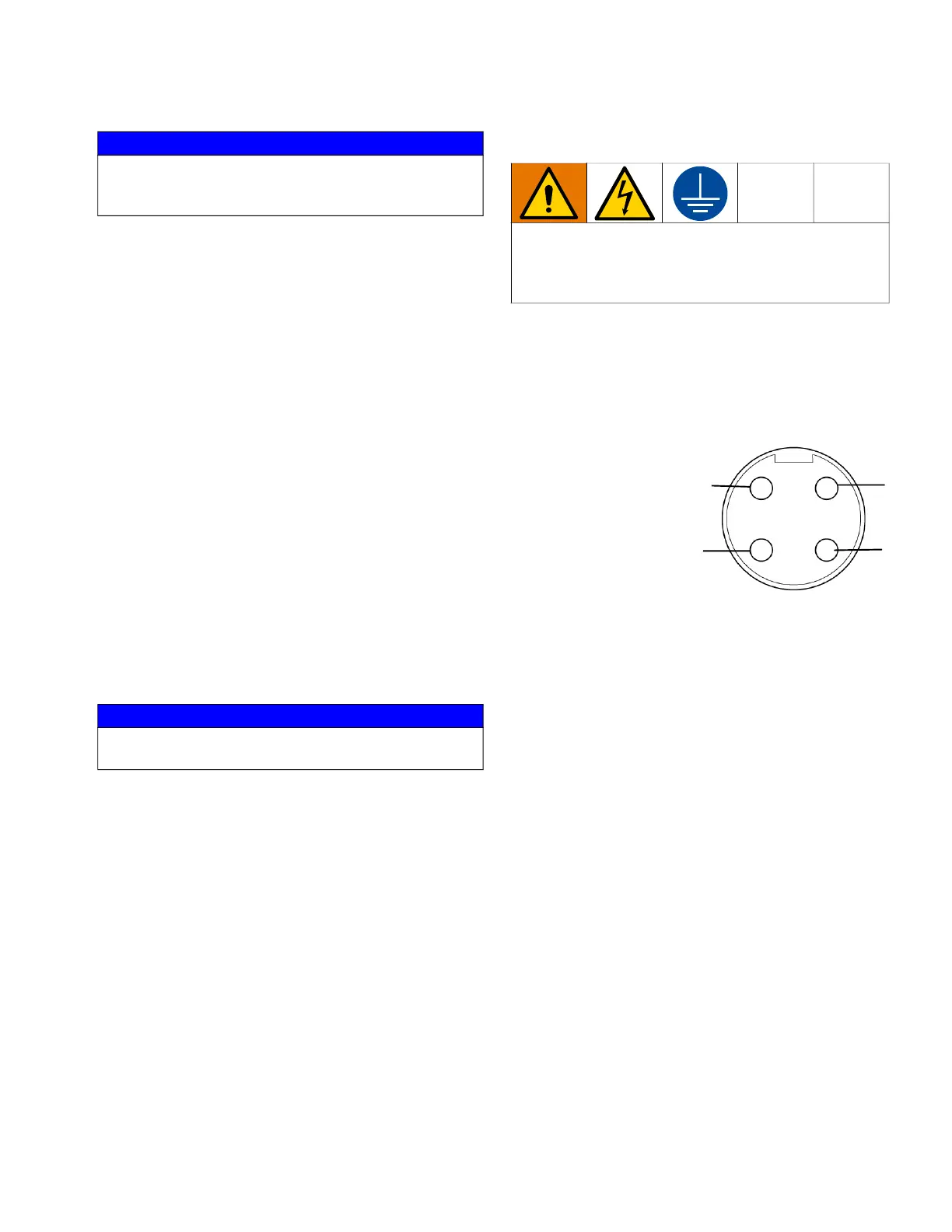
Connecting Cable Wiring Code:
1- Black = Common
2 - White = Normally
Open
3 - Not Used
4 - Green = Ground
NOTICE
Piston is a ground part and all caution must be taken
to avoid nicking, scratching or contaminating this
part or the feeder piston bore.
NOTICE
Do not over torque. Excessive torque will cause
switch failure.
The equipment must be grounded to reduce the risk
of static and electric shock by providing an escape
wire for the electric current due to static build up or in
the event of a short circuit.
1
3
2
4