8 307-043
Air
Motor Service
Pressure Relief Procedure
WARNING
INJECTION
HAZARD
The system pressure must be manually
relieved to prevent the system from
starting or spraying/dispensing acciden
-
tally
. Fluid under high pressure can be injected
through the skin and cause serious injury
. To re-
duce the risk of an injury from injection, splashing
fluid, or moving parts, follow the
Pressure Relief
Procedure
whenever you:
are instructed to relieve the pressure,
stop spraying/dispensing,
check or service any of the system equipment,
or install or clean the spray tip/nozzle.
1.
Close the pump air regulator and the bleed-type
master air valve (required in your system).
2.
Hold a metal part of the spray gun/dispensing
valve firmly to a grounded metal waste container
and trigger the gun/valve to relieve the fluid pres
-
sure.
Before
Y
ou Start
Be
sure you have all necessary parts on hand.
Air Motor Repair Kit 206–728
includes repair parts
for the motor
. Use all the parts in the kit for the
best results. Parts included in the kit are marked
with two asterisks, for example (19**), in the text
and drawings. See
Parts List
on pages 12 – 14.
For best results keep parts marked with one aster
-
isk on hand to reduce down time.
T
wo accessory tools should be used:
Padded
Pliers, 207–579,
are used to grip the trip rod with
-
out damaging its surface, and a 0.145-in. (3.7 mm)
Gauge, 171–818
, is used to assure the proper
clearance between the poppets and the piston.
Disassembly
1.
Flush the pump.
WARNING
T
o reduce the risk of serious injury whenever you
are instructed to relieve pressure, always follow the
Pressure Relief Procedure
above.
2.
Relieve the pressure.
3.
Remove the pump according to the instructions in
the pump manual.
4.
Place the air motor base (F) in a vise with the air
motor up.
5.
Loosen the cap nut (B). Pull up the cap nut, grip
the trip rod (C) with the padded pliers, and screw
the cap nut of
f of the rod.
CAUTION
Do not damage the plated surface of the trip rod (C).
Damaging the surface of the trip rod can result in
erratic air motor operation. Use the special padded
pliers 207–579 to grasp the rod.
6.
Remove the six screws (D) holding the cylinder (E)
to the base (F). Carefully pull the cylinder straight
up of
f of the piston assembly (G).
CAUTION
T
o avoid damaging the cylinder wall, lift the cylinder
straight up of
f of the piston. Never tilt the cylinder as
it is being removed.
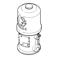
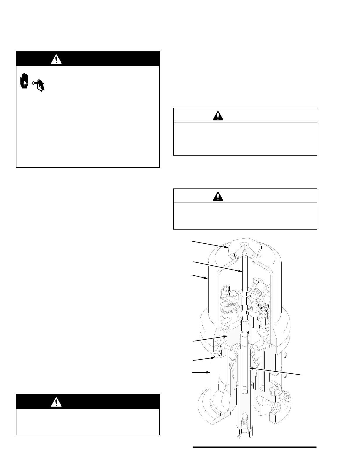
Fig. 2
B
C
E
D
F
A
G
05703
 Loading...