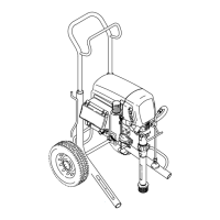
13309941
110 Vac U.K. Motor Control Board
Removal
1.
Relieve pressure; page 5.
Wait 5 minutes before servicing.
2. Fig. 5. Remove four screws (38) and cover (96).
3. Disconnect display connector (A) from motor
control board (95).
4. Remove bottom two screws (39). Disconnect
potentiometer connector (C) from motor control
board (95). Disconnect filter board connector (J)
and power cord connector (D) from ON/OFF
switch (33). Remove control panel (68).
5. Disconnect motor control board power connectors
(K) from filter board (146). Disconnect filter con-
nector (L) from power cord connector (L).
6. Remove top two screws (39) and control box (61).
7. Disconnect transducer connector (E) from motor
control board.
8. Disconnect motor connectors (F, G and H) from
motor control board.
9. Remove five screws (27), three screws (102) and
motor control board.
Installation
1. Fig. 5. Apply small amount of thermal compound
110009 (5) to shaded areas on rear of motor
control board (95).
CAUTION
To reduce risk of motor control board failure, do not
overtighten screws (102) which can damage the
electric components.
2. Install motor control board (95) with five screws
(27). Torque to 9–11 in-lb (1.02 – 1.24 N·m). Install
and torque three screws (102) to values shown in
Fig 5.
3. Connect motor connectors (F, G and H) to motor
control board.
4. Connect transducer connector (E) to motor control
board.
5. Connect motor control board power connectors (K)
to filter board (146). Connect filter connector (L) to
power cord connector (L).
6. Install control box (61) with top two screws (39).
7. Fig. 5. Connect filter board power connector (J)
and power cord connector (D) to ON/OFF
switch (33).
8. Connect potentiometer connector (C) to motor
control board.
9. Install control panel (68) with two screws (39) .
10. Connect display connector (A) to motor control
board (95).
11. Install cover (96) with four screws (38).
110 Vac U.K. Filter Board
Removal
1.
Relieve pressure; page 5.
Wait 5 minutes before servicing.
2. Fig. 5. Remove four screws (38) and cover (96).
3. Disconnect display connector (A) from motor
control board (95).
4. Remove bottom two screws (39). Disconnect
potentiometer connector (C) from motor control
board (95). Disconnect filter board connector (J)
and power cord connector (D) from ON/OFF
switch (33). Remove control panel (68).
5. Disconnect motor control board power connectors
(K) from filter board (146). Disconnect filter con-
nector (L) from power cord connector (L).
6. Remove four screws (163) from filter board (146).
Installation
1. Fig. 5. Connect motor control board power connec-
tors (K) to filter board (146). Connect filter con-
nector (L) to power cord connector (L).
2. Install filter board (146) with four screws (163).
3. Fig. 5. Connect filter board power connector (J)
and power cord connector (D) to ON/OFF
switch (33).
4. Connect potentiometer connector (C) to motor
control board (95).
5. Install control panel (68) with two screws (39).
6. Connect display connector (A) to motor control
board (95).
7. Install cover (96) with four screws (38).
 Loading...