
J
Julie JohnsonAug 17, 2025
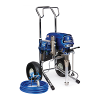
What to do if fluid is spitting from the gun of my Graco Ultra MAX II 490 PC Pro Paint Sprayer?
- MMaurice RodriguezAug 17, 2025
If your Graco Paint Sprayer is spitting fluid from the gun, it could be due to a few reasons. There might be air in the pump or hose, so check and tighten all fluid connections, and cycle the pump slowly during priming. Another possibility is a partially clogged spray tip, which you should clear. Also, ensure that your fluid supply isn't low or empty, and refill it if necessary, then prime the pump.