4. Operation of the Control System
6 / 19
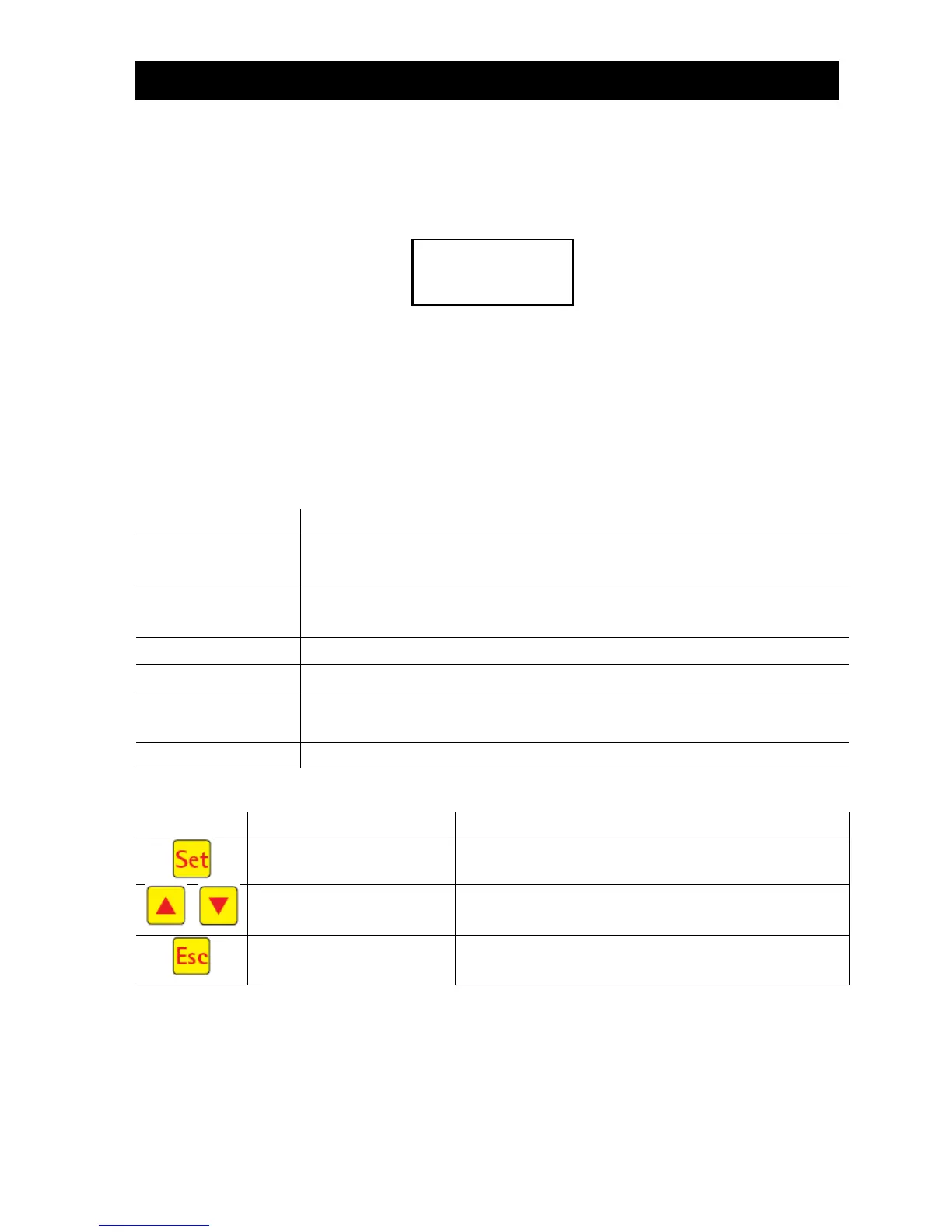
4.1.1 Display of Operating Status
The operating status is indicated by the LEDs (green = operational / red = fault) and as text on the screen.
In normal operating mode (aeration mode), the display appears as follows:
In automatic mode, the liquid crystal display shows the current work phase and the remaining time left in
this phase.
If a fault occurs, the red LED is turned on. A message indicating which component is faulty appears in the
liquid crystal display (e.g. Fault Compressor 0.0A).
4.1.2 The following work phases are displayed
Y3 valve (plug X1.1) is actuated intermittently; the activated sludge is briefly
mixed with the wastewater. This is followed by long pauses (response times).
Y3 valve (plug X1.1) is actuated; the system is aerated in intervals over a long
period of time.
No valves are actuated, the activated sludge settles in the system.
Y4 valve (plug X1.2) is actuated; the clear water is pumped into the drain.
Cycle pause/
holiday mode
Y3 valve (plug X1.1) is actuated; the system is aerated in intervals (considerably
less than in the aeration phase).
Display of remaining time.
Selection of operating mode, confirmation of entries
Display of operating modes and queries Programming of
the system by entering figures
Acknowledgement of entries without saving
Acknowledgement of fault messages
 Loading...