This faucet complies with NSF61/9, ASME/ANSI A112.18.1
and CSA B 125 Standards.
Este grifo se encuentra conforme con losestandares de NSF61/9,
de ASME/ANSI A112.18.1 y de CSA B 125.
Installation Instructions Instrucciones de Instalación
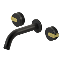
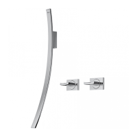
THERMOSTATIC SET
CONJUNTO TERMOSTÁTICO
5
IOG 5013.20
E
~
ESPANOL
ENGLISH
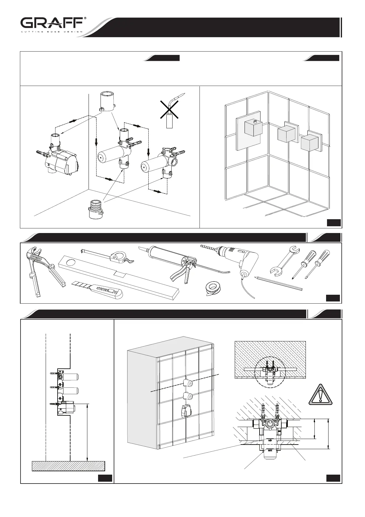
For the installation of every valve irrespective of the thermostat
localization use dedicated pipe connectors. Do not use gas burner while
installing pipes (Fig. D).
Para instalar cada una de las válvulas independientemente de la
ubicación del termóstato hay que usar los manguitos dedicados.
Durante la instalación de los tubos no se puede usar el
quemador (Fig. D).
4
FOR ASSEMBLY YOU WILL NEED
PARA EL MONTAJE SE NECESITAN
F
5
ASSEMBLY DIMENSIONS
DIMENSIONES DE MONTAJE
MIN 45-1/4”
(MIN 1150 mm)
MAX 49-3/16”
(MAX 1250 mm)
Height of the assembly
Altura de montaje
MIN
MAX
MIN
MAX
3-3/8”
(85 mm)
Finishing partition min.
El mínimo de la pared de acabado
Finishing partition max.
Maximum de la pared de finition
Finishing partition
Pared de finition
4-5/16”
(110 mm)
1.1 1.2
Rev. 3 October 2018