Graham Corporation
16
3.3 Service Liquid Requirements
A) Flow Rates
Service liquid flow rates depend on the type of piping arrangement used, the size and operating
speed of the pump, and the allowable temperature rise through the pump. Nominal flow rates
for standard pumps and compressors at normal conditions are given in Table 1.
Service liquid flow rates and the temperature rise are important because of their effect on pump
performance. Too little flow will result in loss of capacity. Too much flow will result in
excessive horsepower requirements.
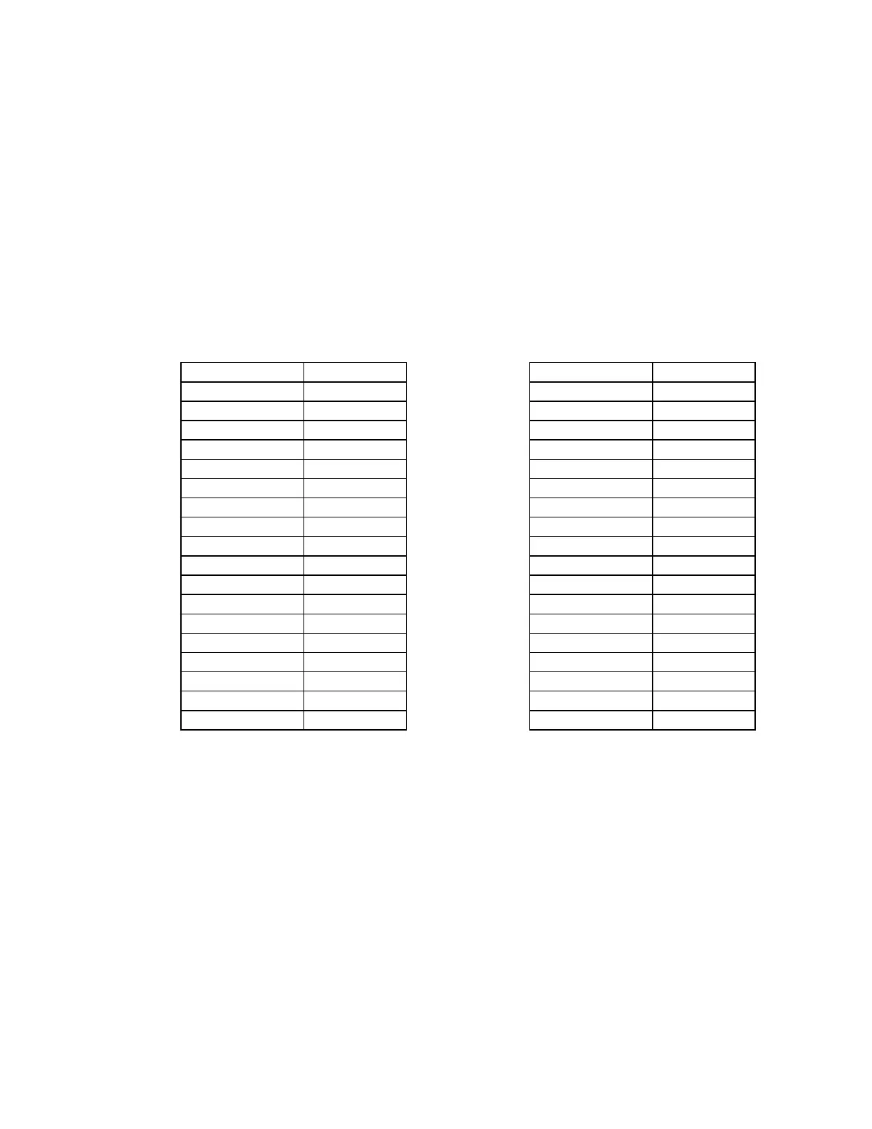
Service Liquid Flow Rates*
Single Stage Pumps Two Stage Pumps
Pump Model
USGPM
Pump Model
USGPM
PV31040 4 PV32040 4
PV31080 4 PV32080 4
PV31120 6 PV42120 6
PV41160 6 PV42160 6
PV51080 8 PV52120 8
PV51120 8 PV52160 8
PV51160 10 PV52200 10
PV51200 11 PV62160 20
PV61255 20 PV62240 24
PV61335 25 PV72200 30
PV71300 30 PV72300 30
PV71400 30 PV72400 30
PV81360 45 PV72500 35
PV81460 50 PV82350 35
PV81560 55 PV82450 40
PV91540 100 PV82550 45
PV91670 100 PV92540 100
PV92670 100
* Flowrates apply to PV or PC design. For units in m
3
/hr, multiply USGPM by 0.227
Table 1
B) Flow Control
If a flow device is not used to measure the service liquid quantity to the pump, a regulating
valve and compound gauge in the service liquid line can be used to approximate the flowrate.
For pump operating pressures between atmospheric and 400 mmHgA, the reading on the
compound gauge should be in the range of 2" HgV to 5 psig (709 mmHgA to 0.35 barg). For
operating pressures below 400 mmHgA, the compound gauge reading should be in the range of
15" HgV to 2 psig (379 mmHgA to 0.14 barg). This method is only an approximation of the
service liquid quantity. The actual operating conditions will dictate the amount of sealant liquid
required and also the compound gauge reading.
 Loading...