Graham Corporation
7
Install the piping for the shaft seal coolant as required. Refer to section 2.8 regarding the shaft
seal coolant piping requirements.
The location of the installation or the storage of the pump should be in an area that will
not subject the pump to freezing.
Verify the pump’s rotation direction by checking the arrow on the shaft end casing. Refer to
section 2.10 concerning the electrical requirements.
2.5 Coupling Alignment
CAUTION:
TO PREVENT PERSONAL INJURY, DO NOT OPERATE THE PUMP
WITHOUT PROPERLY GUARDING THE DRIVE COUPLING(S).
Pumps supplied from the factory packaged with a motor have had the shafts aligned prior to
shipment. This ensures that alignment can be done in the field. It is required that the shaft
alignment be rechecked after mounting on a level foundation and prior to start-up.
When a gear reducer is supplied between the pump and motor, they are aligned at the factory
and must be realigned after installation. The gear reducer should be aligned to the pump first
and then the motor should be aligned to the gear reducer.
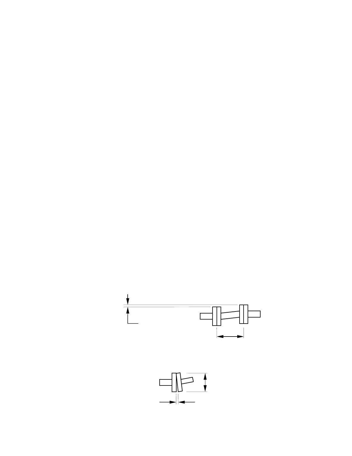
For smoother operation and longer life of the coupled equipment, the following maximum
misalignment tolerances are recommended:
The maximum allowable parallel shaft misalignment for standard couplings is
±0.002" (0.05 mm) and for spacer couplings is ±0.001" per inch (0.025 per mm) of
spacer length.
The maximum allowable angular shaft misalignment is ±0.0005" per inch
(0.013 per mm) of coupling diameter.
±0.002" or
±0.001" x L
L
D
±0.0005" x D
 Loading...