Graham Corporation
26
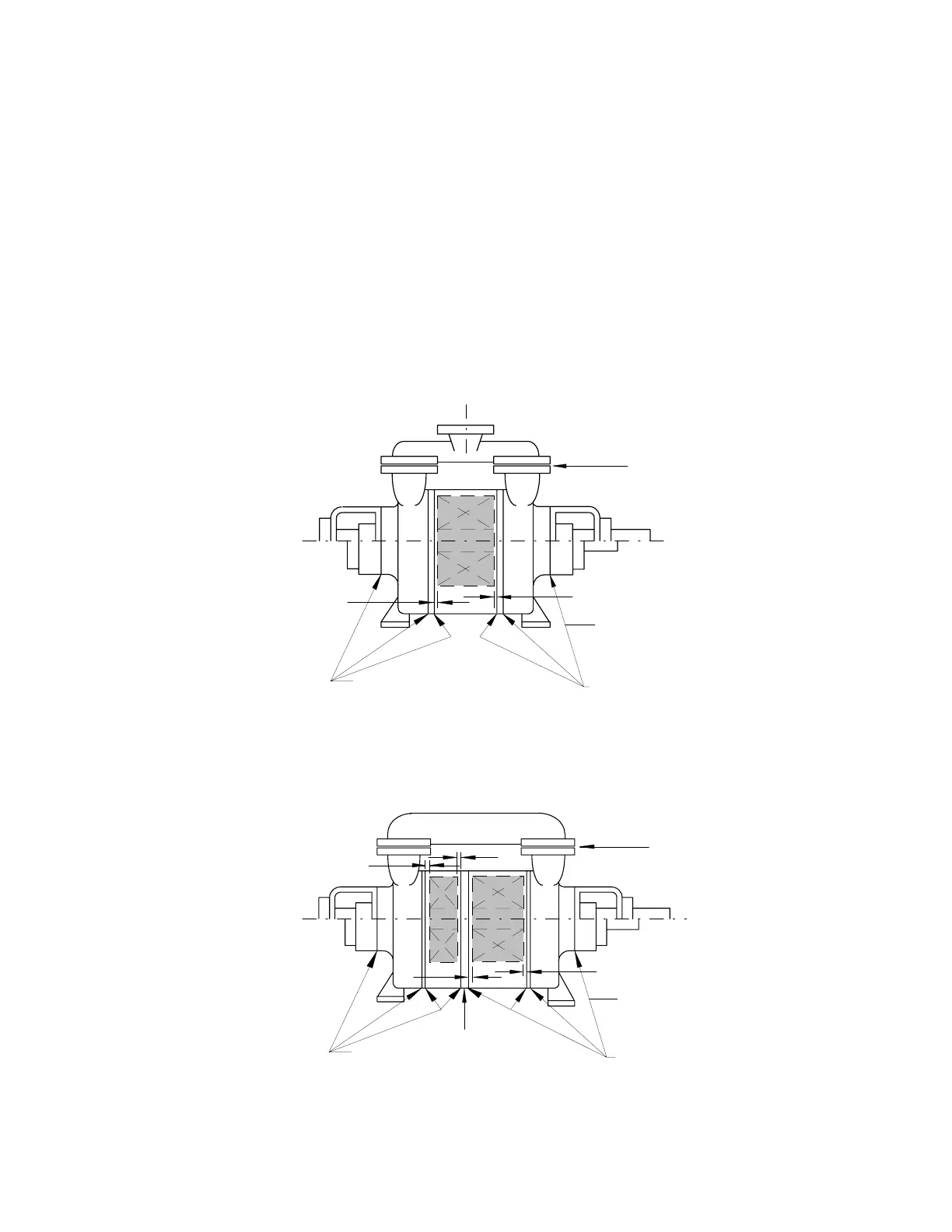
A) Gasketed Pumps
The critical impeller end clearance locations and typical gasket locations are shown in Figures 8
and 9. The gaskets between the impeller casings and the end plates determine the impeller end
clearances. Check and record the thickness and quantity of these gaskets at each joint when
dismantling. The gaskets may be held in place with grease during re-assembly. The gasket
thicknesses used on pumps of standard materials of construction are 0.008" to 0.010" (0.2 to
0.25 mm). The gasket thicknesses used on high alloy pumps are 0.015" to 0.018" (0.38 to 0.46
mm).
Do not use joint sealing compound to replace a gasket as the clearances in the pump will be
affected.
Gaskets
Gaskets
Series 1
Series 2
Single Stage
Figure 8
Series 2 Only
Both Ends
*
*
Gaskets
Gaskets
Series 1
Series 2
Two Stage
Figure 9
Gasket for two piece
interstage casing design
Gaskets
Series 2 Only
Both Ends
*
*
*
*
Gaskets
* Impeller clearance locations.
 Loading...