Repair Manual MSG 90.6PG Commercial Vehicles, Omnibuses – November 2017
Material no. 1153450_c
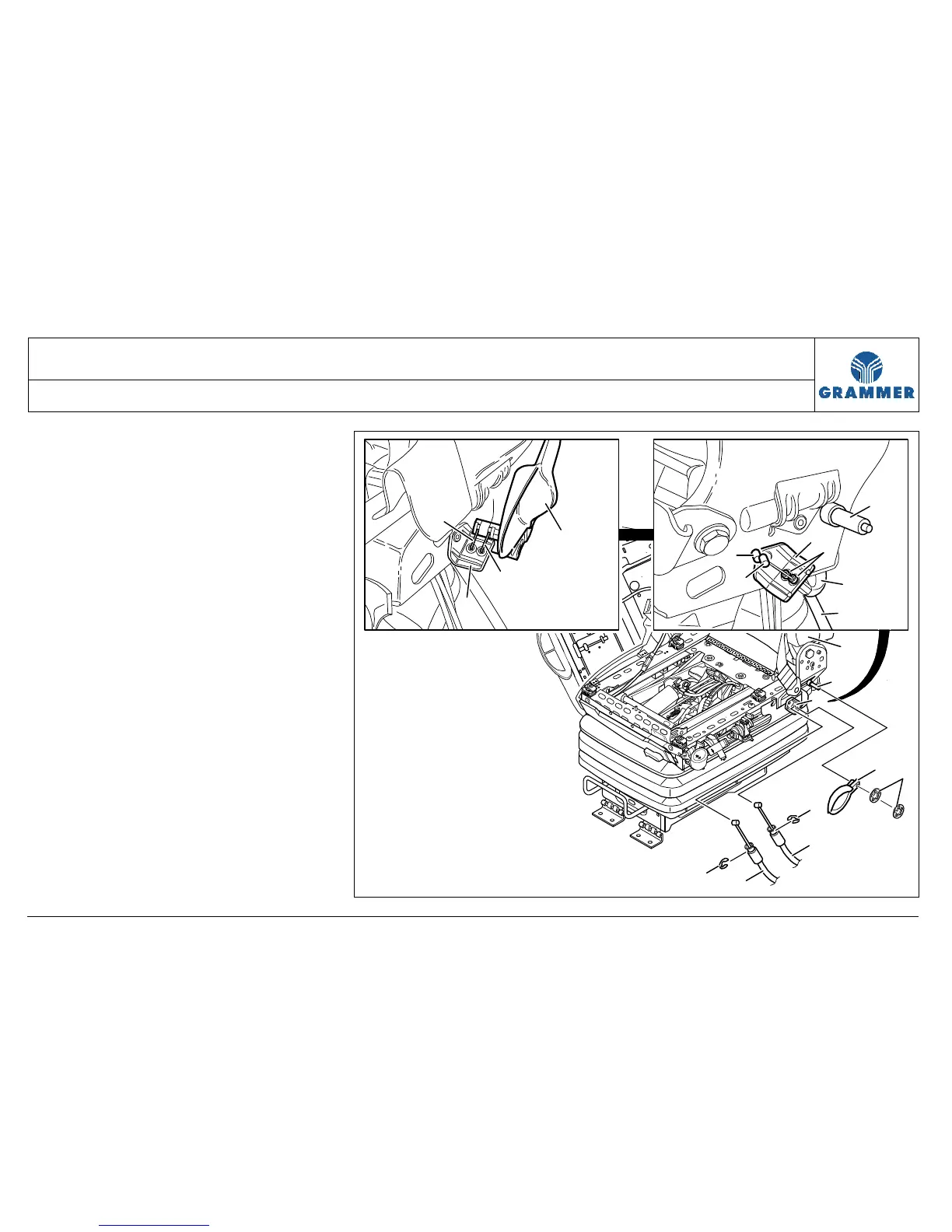
3.13 Bowden pull wire and lever for backrest adjustment –
removal and installation
Page 5 of 6
REMOVAL / INSTALLATION TABLE OF CONTENTS
Remove two axial locking rings (6) at
the stud (4).
Installation notes:
• Replace the axial locking ring (6).
• Press the axial locking ring (6)
onto the stud (4) with the curve
pointing to the lever for backrest
adjustment (7).
11 Pull off the lever for backrest
adjustment (7) at the stud (4).
12 Detach the left and rig
wires (1, 2) at the lever for backrest
adjustment (7).
Note:
The left Bowden pull wire (1) must
be hung into the left drill hole and
the right Bowden pull wire (2) must
be hung into the right drill hole at the
lever for backrest adjustment (7).
5
1
2
1
2
4
8
5
1
7
2
7
4
3
5
6
2
8
1
8
2184