Repair Manual MSG 90.6PG Commercial Vehicles, Omnibuses – November 2017
Material no. 1153450_c
3.32 Bearing support with backrest locking mechanism and hook-in
function – removal and installation
Page 10 of 14
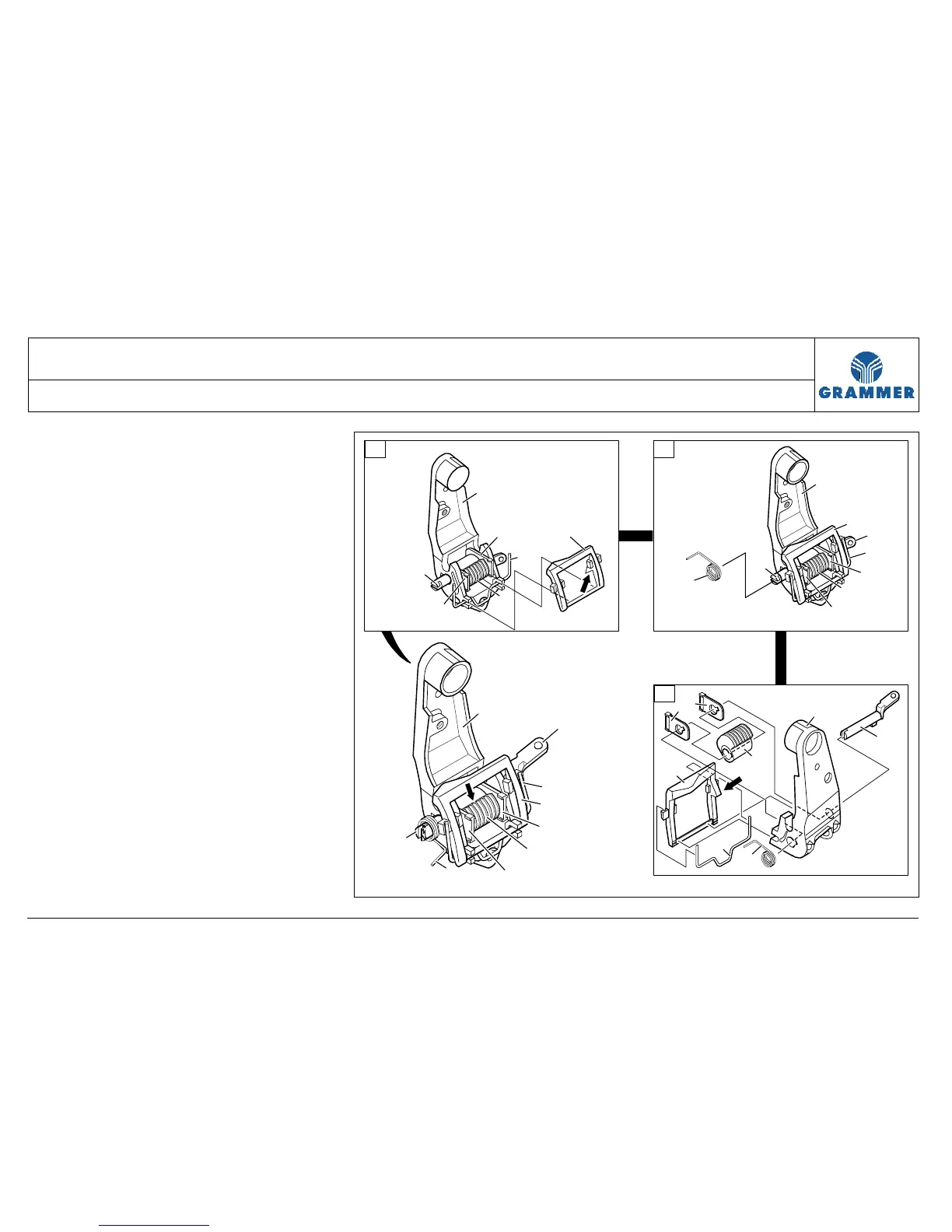
1.4 Hang the transversal bracket of the
torsion spring (D/16) into the hinge
of the bearing support (D/1).
Note:
The bend at the transversal bracket
of the torsion spring (D/16) must
point towards the bearing
support (D/1).
1.5 Insert the bracket (D/17) into the
hinge of the bearing support (D/1)
and hang in the legs of the torsion
spring (D/16) into the lateral hook of
the bracket (D/17).
The torsion spring (16) presses the
bracket (17) onto the bearing
support (1).
Note:
The nose (D/arrow) on the side of
the bracket (D/17) must point
towards the bearing support (D/1)
and must be located on the inserting
side of the catch element (D/15).
14
2
13
18
15
8
16
1
17
14
13
16
15
14
13
1
14
16
15
15
7
17
14
17
1
16
15
14
14
13
7
14
15
2235
D
E
F