Repair Manual MSG 90.6PG Commercial Vehicles, Omnibuses – November 2017
Material no. 1153450_c
3.32 Bearing support with backrest locking mechanism and hook-in
function – removal and installation
Page 11 of 14
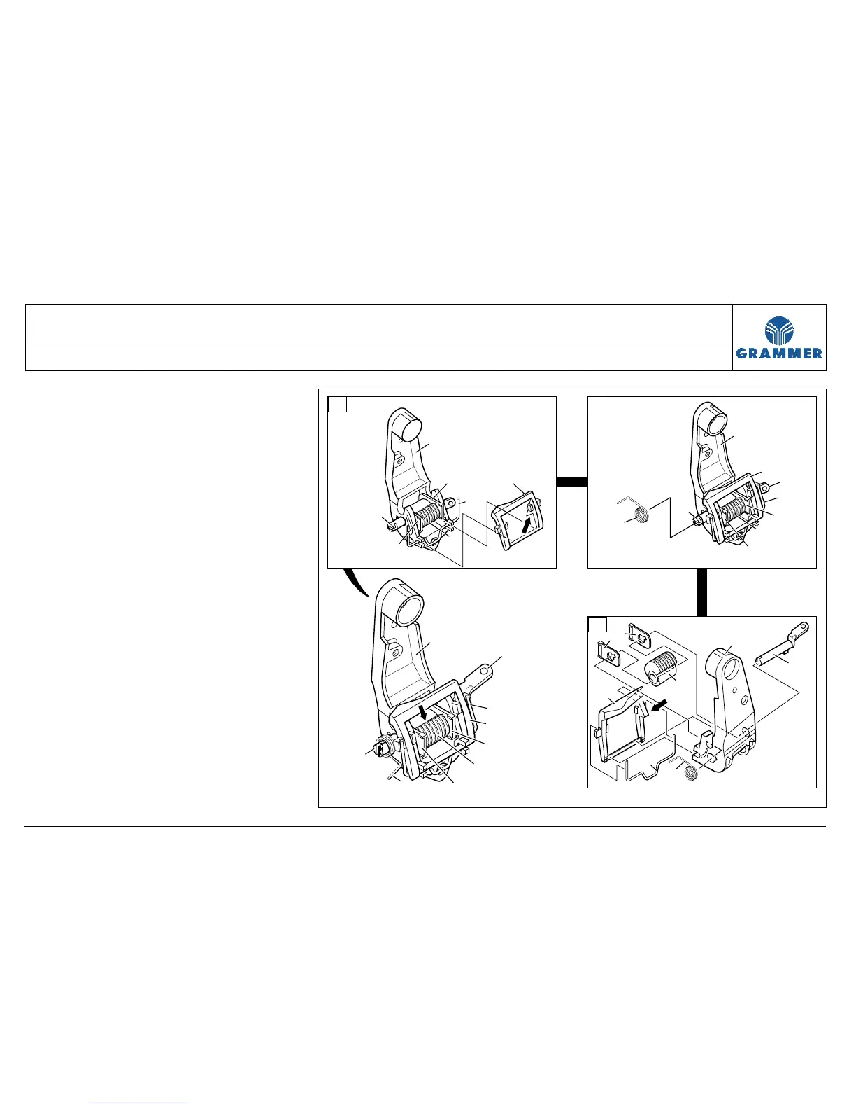
1.6 Insert the short leg of the retaining
spring (E/7) into the catch element
(E/15).
Notes:
• The long leg of the retaining spring
(E/7) must point towards the bearing
support (E/1) and to the back.
• When it is installed, the retaining
spring (7) must press upwards the
engaging surface (arrow) of the
lock (13).
2 Assembly of the left bearing
support (2):
Assemble the left bearing support
(F/2) according to steps 1.1 to 1.6 with
the retaining spring (F/8) and the
components (F/13, F/14, F/15, F/16
and F18) laterally reversed.
14
2
13
18
15
8
16
1
17
14
13
16
15
14
13
1
14
16
15
15
7
17
14
17
1
16
15
14
14
13
7
14
15
2235
D
E
F