19
Section 15 System operation and Troubleshooting
2. Sensors (Thermistors/Pressure Transducer)
1. Control Logic Description
● The variable speed system adopts the same 24VAC control as any conventional Heat Pump.
● The compressor’s speed is controlled based on coil pressures monitored by pressure transducer. To insure
stable and adequate capacity, the compressor speed will modulate relative to evaporator pressure during
cooling operation and relative to condensing pressure during heating operation. The target pressure can auto-
matically adjust based on compressor operation so optimal capacity can be achieved. Target pressure can
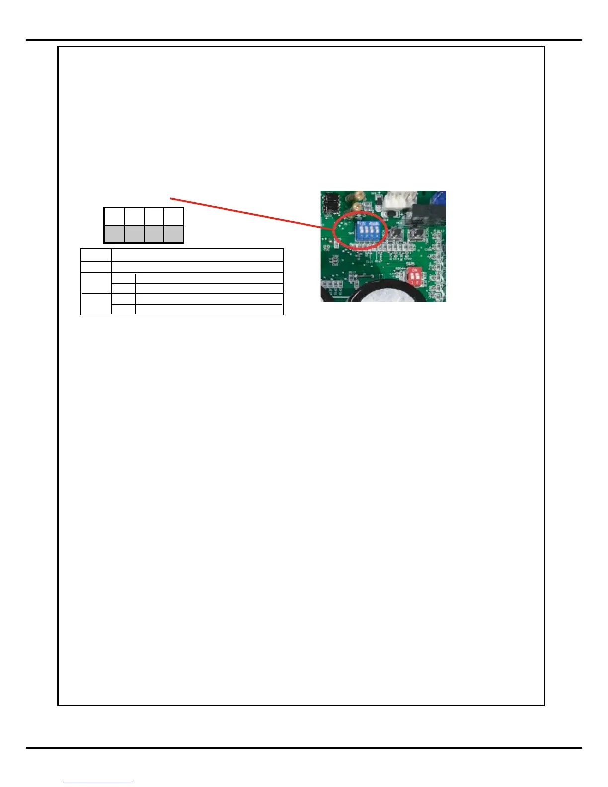
manually be adjusted (SW4) to achieve improved dehumidification and capacity demands.
● T3 = Outdoor Coil Temperature (Table 1)
o High/Low temperature protection
o Outdoor fan control (cooling mode)
o Defrost control (heating mode)
o Ambient Temperature forecast
● T4 = Ambient Temperature (Table 1)
o Operating condition permission
o Defrosting condition permission
o Outdoor fan control (heating mode)
● T5 = Compressor Discharge Temperature (Table 2)
o High/Low temperature protection
o Electronic Expansion Valve (EXV) control (ODU)
● TF = IPM Radiator Temperature) (Table 2)
o Inverter High Temperature Protection
● Pressure transducer (Table 3)
o Operating speed control
o Electronic Expansion Valve (EXV) control (ODU)
o High pressure protection (heating mode)
o Low pressure protection (cooling mode)
ON
OFF
1 2
3 4
SW4
SW4-2
SW4-3
Not used
SW4-4
OFF
ON
Normally cooling/heatin g
OFF
ON
Accelerated cooling/heatin g
Adaptive capacity output disable
Adaptive capacity output enabl e
SW4-1
Not used