INSTALLATION INSTRUCTIONS Gas Furnace: WFAR
20 440 01 7104 02
Specifications subject to change without notice.
+
+
+
Condensing
Furnace
-
-
-
-
-
ÄÄÄÄÄÄÄÄÄ
ÄÄÄÄÄÄÄÄÄ
ÄÄÄÄÄÄÄÄÄ
ÄÄÄÄÄÄÄÄÄ
ÄÄÄÄÄÄÄÄÄ
ÄÄÄÄÄÄÄÄÄ
ÄÄÄÄÄÄÄÄÄ
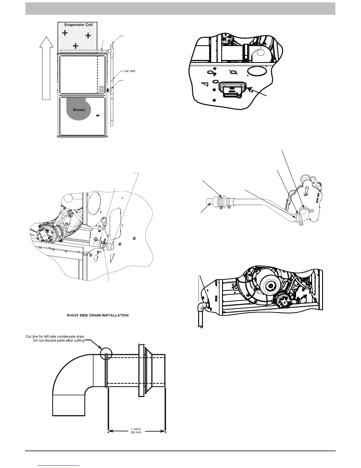
Evaporator Coil
+
+
+
< +
< +
< +
+
Blower
-
3/4”
PVC
3/4
3/4
3/4
3/4
3/4
3/4
+ = Positive pressure
< + = Pressure lower than areas with +
ï = Negative pressure
+
DIRECTION
OF
AIRFLOW
3/4”
PVC
Open
standpipe
(Optional
when
coil
drain
is
not
connected
to
furnace
drain.)
TEE
(1/2”
CPVC
to
3/4”
PVC
adapter
from
loose
parts
bag.)
L14F027
Example of Field Drain Attachment (continued)
INSTALL CLAMPS ON DRAIN ELBOW
ATTACH DRAIN ELBOW TO CONDENSATE
DRAIN TRAP
PULL DRAIN STUB
THROUGH CASING
OPEN SPRING CLAMP
INSERT FACTORY--SUPPLIED 1/2--IN. CPVC
TO 3/4--IN. PVC ADAPTER OR 1/2--IN. CPVC PIPE
*CLAMP MAY BE LOCATED ON OUTSIDE OF DRAIN ELBOW
L12F022
Figure 15 -- Formed Rubber Drain Grommet
A11581
Figure 16 -- Modify Rubber Drain Elbow
Remove knockout.
Install grommet before
relocating condensate
trap.
NOTE: Trap grommet is required only for direct-vent
applications.
A11582
Figure 17 -- Accessory Horizontal Drain Trap Grommet
s
TRAP, DRAIN ELBOW WITH DISCHARGE PIPE
Attach elbow to condensate trap
Cut formed end off
condensate drain
elbow
Connect short end
of “Z” pipe to modified
drain elbow
Factory supplied 1/2--in. CPVC to
3/4--in. PVC adapter
LEFT SIDE DRAIN ROUTED BEHIND INDUCER
Formed end of grommet
Open spring clamp. Insert
1/2--in. to 3/4--in. CPVC to
PVC adapter or 1/2--in.
CPVC pipe
Modified drain elbow connect to
condensate trap and “Z” pipe
Formed end of
grommet
NOTE: Remove Inducer Housing for easier access, if desired.
L12F015
Figure 18 -- Drain Trap Connection and Routing
(Appearance May Vary)