FCC Test Report #: SHE-1205-10825-FCC
Prepared for Grandstream Networks, INC
Prepared by ECMG Electronic Technical Testing Corp (Shenzhen) Page 28 of 31
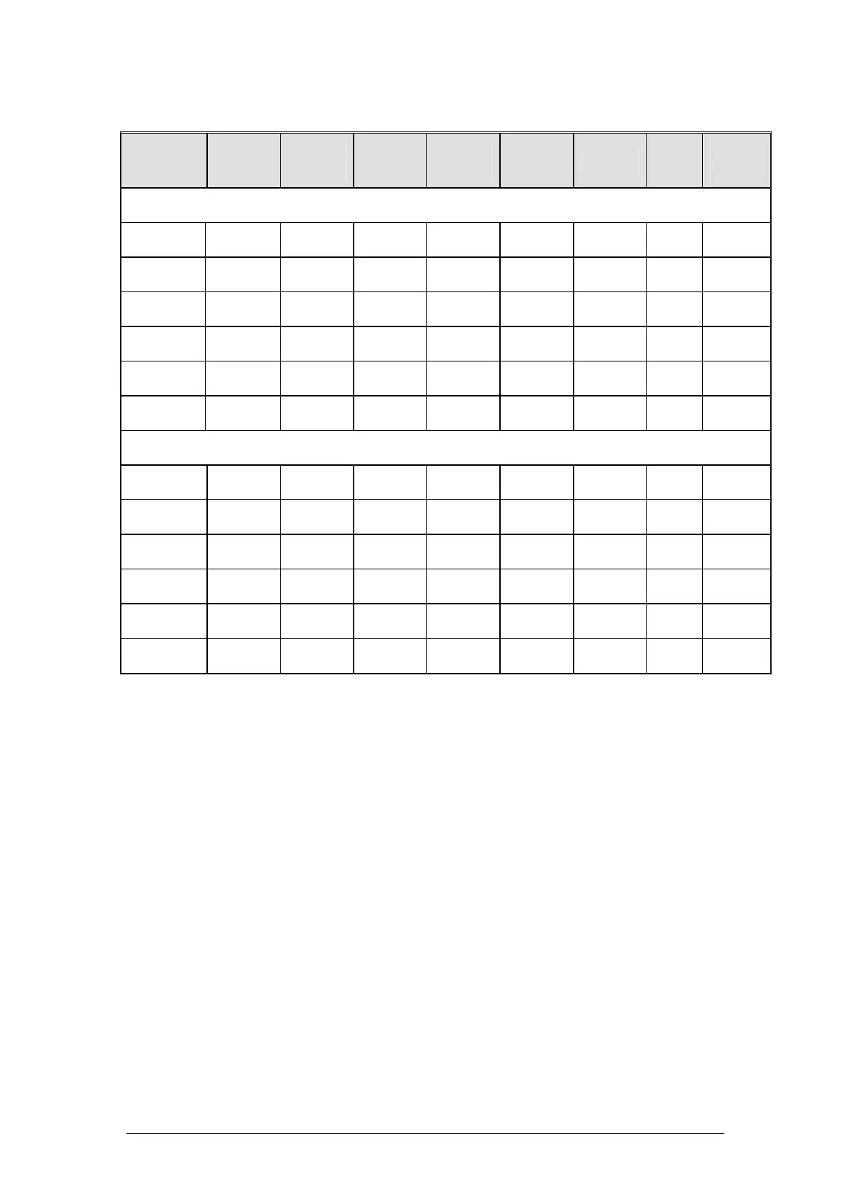
Above 1GHz:
Frequency
(MHz)
Cable
Loss
(dB)
Antenna
Factor
(dB)
Preamp
Factor
(dB)
Reading
Level
(dBuV/m)
Emission
Level
(dBuV/m)
Limit
(dBuV/m)
Margi
n
(dB)
Antenna
Polariza
tion
(H/V)
Peak Measurement
1.060 1.40 24.1 33.6 59.79 51.69 74 -22.31 H
1.330 1.53 25.1 33.6 61.45 54.48 74 -19.52 H
1.600 1.80 27.0 33.6 56.08 51.28 74 -22.72 H
1.076 1.40 24.1 33.6 56.8 48.70 74 -25.3 V
1.330 1.53 25.1 33.6 58.08 51.11 74 -22.89 V
1.390 1.56 25.3 33.6 62.36 55.62 74 -18.38 V
Average Measurement
1.060 1.40 24.1 33.6 40.49 32.39 54 -21.61 H
1.330 1.53 25.1 33.6 41.17 34.20 54 -19.8 H
1.600 1.80 27.0 33.6 40.76 35.96 54 -18.04 H
1.076 1.40 24.1 33.6 41.86 33.76 54 -20.24 V
1.330 1.53 25.1 33.6 38.08 31.11 54 -22.89 V
1.390 1.56 25.3 33.6 43.46 36.72 54 -17.28 V
Note:
1. The field strength is calculated by adding the Antenna Factor,
Cable Factor & Preamplifier. The basic equation with a sample
calculation is as follows: Emission Level =Reading Level + Antenna
Factor + Cable Loss –Preamplifier Factor.
2. The limits shown are based on Peak value and Average value
detector above 1GHz,the bandwidth of Test Receiver was set at
1MHz above 1GHz.
3. The other emission levels are 20dB below the official limits that are
not reported.
 Loading...