G.R.A.S. Sound & Vibration
Pistonphone Types 42AA/42AA-S1 - Page 12
Wait approximately for 15 seconds for the static pressure in both the Pistonphone and the
microphone to stabilise, and for the microphone itself to stabilise within the coupler.
The static pressure within the coupler volume is equalised via an air-equalisation tube located
under the cap which protects the pistons and retention spring shown in Fig. 2.1.
With the Pistonphone switched on, the microphone is subjected to a sound pressure level L
C
given as the sum of the Pistonphone’s nominal sound pressure level L
N
(found on the piston-
phone’s calibration chart as “Sound Pressure Level”), the static pressure correction L
B
and the
volume correction L
V
, i.e.:
3.3.4 ⅛-inchMicrophones
To calibrate a ⅛-inch measurement microphone, rst loosen the microphone retention collar as
shown in Fig. 3.2. Then insert the ⅛-inch microphone adapter (RA0069) into the ½-inch coupler
as shown on Fig. 3.4. Make sure that the adapter is all the way in, then tighten the microphone
retention collar so that the adapter is held rmly in place. Insert the ⅛-inch microphone into the
⅛-inch adapter.
Switch the Pistonphone on via the on/off (I/0) button. The LED above the on/off button is a
dual-colour LED for showing red or green. The LED shows green if the Pistonphone is operating
properly at the specied frequency. If the LED shows red or ashing red, the Pistonphone is not
operating at the specied frequency and the batteries should be changed (see section 3.2).
Wait approximately for 15 seconds for the static pressure in both the Pistonphone and the
microphone to stabilise, and for the microphone itself to stabilise within the coupler.
The static pressure within the coupler volume is equalised via an air-equalisation tube located
under the cap which protects the pistons and retention spring shown in Fig. 2.1.
With the Pistonphone switched on, the microphone is subjected to a sound pressure level L
C
given as the sum of the Pistonphone’s nominal sound pressure level L
N
(found on the piston-
phone’s calibration chart as “Sound Pressure Level”), the static pressure correction L
B
and the
volume correction L
V
, i.e.:
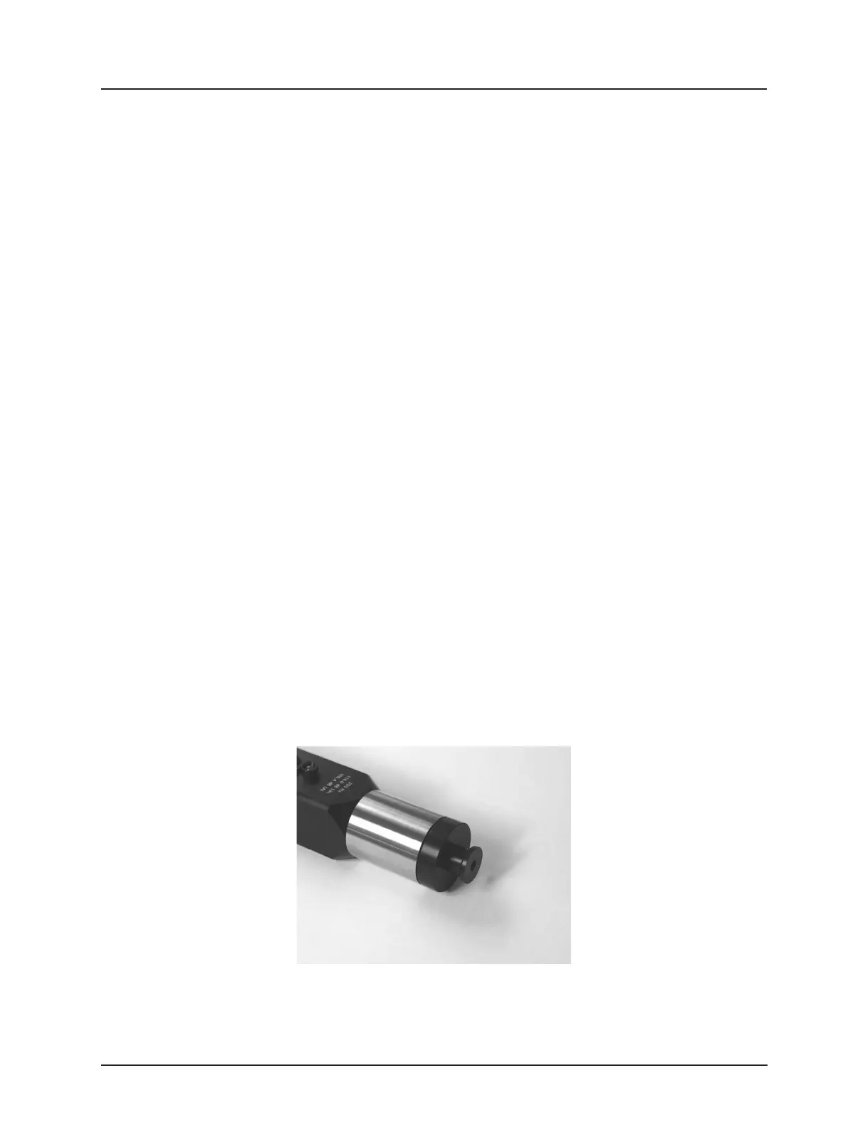
Fig. 3.5 ⅛-inch microphone adapter
inserted in the coupler
L
C
= L
N
+ L
B
+ L
V
(5)
L
C
= L
N
+ L
B
+ L
V
(6)