G.R.A.S. Sound & Vibration
Pistonphone Types 42AA/42AA-S1 - Page 13
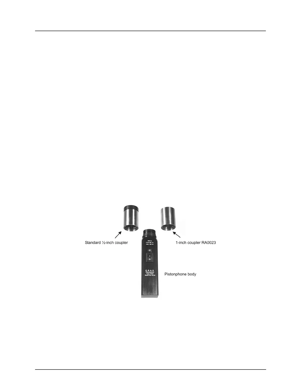
3.3.5 1-inch Microphones
To calibrate a 1-inch measurement microphone, the standard ½-inch coupler has to be replaced
by the optional 1-inch coupler
1
(RA0023), see Fig. 3.6. Unscrew the ½-inch coupler from the
Pistonphone body. The pistons and retention spring shown in Fig. 2.1 are protected so there
is no risk of accidentally damaging these parts when removing the coupler. Screw the 1-inch
coupler (RA0023) onto the Pistonphone body. Then insert the 1-inch microphone into the 1-inch
coupler. Make sure that the microphone is all the way in.
Switch the Pistonphone on via the on/off (I/0) button. The LED above the on/off button is a
dual-colour LED for showing red or green. The LED shows green if the Pistonphone is operating
properly at the specied frequency. If the LED shows red or ashing red, the Pistonphone is not
operating at the specied frequency and the batteries should be changed (see section 3.2).
Wait approximately for 15 seconds for the static pressure in both the Pistonphone and the
microphone to stabilise, and for the microphone itself to stabilise within the coupler.
The static pressure within the coupler volume is equalised via an air-equalisation tube located
under the cap which protects the pistons and retention spring shown in Fig. 2.1.
With the Pistonphone switched on, the microphone is subjected to a sound pressure level L
C
given as the sum of the Pistonphone’s nominal sound pressure level L
N
(found on the piston-
phone’s calibration chart as “Sound Pressure Level”), the static pressure correction L
B
and the
volume correction L
V
, i.e.:
Fig. 3.6 1-inch and ½-inch couplers
1
The 1-inch coupler is individual calibrated with the pistonphone, and these must be considered as a pair.
L
C
= L
N
+ L
B
+ L
V
(7)